The device is designed to search for alternating current electrical networks underground and in the channels of concrete and brick buildings, their location and depth.
Before searching for the route, an audio frequency voltage of sufficient power should be applied to disconnected cable lines, and the end of the line should be temporarily closed; this should also be done in case of possible mechanical damage; the electromagnetic field in the damaged area is always several times higher than in a healthy section of the line.
The principle of operation of the device is based on the conversion of the electromagnetic field of the electrical network with a frequency of 50 Hz into an electrical signal, the level of which depends on the voltage and current in the conductor, as well as on the distance to the radiation source and the shielding factors of soil or concrete.
The device circuit consists of an electromagnetic field sensor BF1, a pre-amplifier on a transistor VT1, a power amplifier DA1 and an output control device consisting of a sound analyzer on headphones BA1, a light peak indicator HL1 and a galvanic power indicating device - PA1. To reduce distortion of the electromagnetic field signal, negative circuits were introduced into the amplifier circuits. feedback. The use of a powerful low-frequency amplifier at the output allows you to connect a load of any resistance and power.
Installation resistors and regulators are introduced into the circuit to optimize the operating mode of the device circuit. The device can estimate the depth of the electrical network from the surface of the earth.
To power the device circuit, a current source of the Krona type at 9 volts or a KBS at a voltage of 2 * 4.5 volts is sufficient.
To eliminate accidental discharge of batteries, the circuit uses double shutdown: by opening the positive power bus of the power bus when the BA1 headphones are turned off.
The BF1 electromagnetic sensor is used from high-impedance telephone headphones of the TON-1 type with the metal membrane removed. It is connected to the pre-amplifier on transistor VT1 through the coupling capacitor C2. Capacitor C3 reduces the level of high-frequency interference, especially radio interference. The amplifier on transistor VT1 has voltage feedback from the collector to the base through resistor R1; when the voltage on the collector increases, the voltage on the base increases, the transistor opens and the collector voltage decreases. Power is supplied to the amplifier through load resistor R2 from filter C1, R4. Resistor R3 in the emitter circuit of transistor VT1 mixes the characteristics of the transistor and, due to the negative voltage level, slightly reduces the gain at signal peaks. The pre-amplified electromagnetic field signal is supplied through galvanic isolation capacitor C4 to the gain regulator R5 and then through resistor R6 and capacitor C6 to input (1) of the analog power amplifier chip DA1. Capacitor C5 reduces frequencies above 8000 Hz for better signal perception.
The audio power amplifier on the DA1 chip with an internal device for protecting against short circuits in the load and overload allows you to amplify the input signal with good parameters to a value sufficient to operate a load of up to 1 watt.
The distortion in the signal introduced by the amplifier during operation depends on the value of the negative feedback. The OS circuit consists of resistors R7, R8 and capacitor C7. With resistor R7 it is possible to adjust the feedback coefficient based on the quality of the signal.
Capacitor C9 and resistor R8 eliminate self-excitation of the microcircuit at low frequencies.
Through the isolation capacitor C10, the amplified signal is supplied to the load BA1, the level indicator PA1 and the LED indicator HL1.
Electrodynamic headphones are connected to the output of the amplifier via connector XS1 and XS2, the jumper in XS1 closes the power supply circuit from battery GB1 to the circuit. The HL1 indicator light monitors the presence of output signal overload.
Galvanic device PA1 indicates the signal level depending on the depth of the electrical network and is connected to the output of the amplifier through an isolation capacitor C11 and a voltage multiplier on diodes VD1-VD2.
There are no scarce radio components in the power grid search device: the BF1 electromagnetic field receiver can be made from a small-sized matching transformer or an electromagnetic coil.
Resistors type C1-4 or MLT 0.12, capacitors type KM, K53.
Reverse conduction transistor KT 315 or KT312B. Pulse diodes for current up to 300 mA.
A foreign analogue of the DA1 chip is TDA2003.
The PA1 level device is used from the recording level indicator of tape recorders with a current of up to 100 μA.
HL1 LED of any type. Headphones BA1 - TON-2 or small-sized ones from players.
A correctly assembled device begins to work immediately, by placing the electromagnetic field sensor on the power cord of the switched-on soldering iron, set resistor R7 to the maximum volume of the signal in the headphones, when
middle position of the R5 “Gain” regulator.

All radio components of the circuit are located on printed circuit board In addition to the BF1 sensor, it is installed in a separate metal box. The power battery - KBS is fixed outside the case with a bracket. All housings with radio components are mounted on an aluminum rod.
You can start testing the power grid search device without leaving your home; just turn on the light of one of the lamps and clarify the route in the wall and ceiling from the switch to the lamp, and then proceed to search for routes underground in the courtyard of the house.
Literature:
1. I. Semenov Measurement of high currents. "Radiomir" No. 7 / 2006 p. 32
2. Yu.A. Myachin 180 analog microcircuits. 1993
3. V.V. Mukoseev and I.N. Sidorov Marking and designation of radioelements. Directory. 2001
4. V. Konovalov. Device for searching electrical wires - Radio, 2007, No. 5, S41.
5. V. Konovalov. A. Vanteev Search for underground power networks, Radiomir No. 11, 2010, C16.
Description of the locator circuit. In Fig. 1 tone generator circuit. The RC generator is assembled on transistor T1 and operates in the range of 959 – 1100 Hz. Smooth frequency adjustment is carried out by a variable resistor R 5. In the collector circuit of transistor T 2, which serves to match the generator T1 with the phase inverter T3, using switch Bk1, relay contacts P1 can be connected, designed to manipulate the oscillations of the generator T1 with a frequency of 2-3 Hz. Such manipulation is necessary for clear identification of signals in the receiving device in the presence of interference and interference from underground cables and overhead AC circuits. The manipulation frequency is determined by the capacitance of capacitor C7. The pre-terminal and final cascades are made according to a push-pull circuit. The secondary winding of the output transformer Tr3 has several outputs. This allows you to connect to the output various loads that may be encountered in practice. When working with cable lines, a higher voltage connection of 120-250 Volts is required. Fig. 2 shows a circuit of a network power supply with stabilization of the 12V output voltage.

Schematic diagram of a receiving device with a magnetic antenna - Fig. 3. It contains an oscillating circuit L1 C1. The audio frequency voltage induced in circuit L1 C1 through capacitor C2 is supplied to the base of transistor T1 and is further amplified by subsequent stages on transistors T2 and T3. Transistor T3 is loaded onto the headphones. Despite the simplicity of the circuit, the receiver has quite high sensitivity. Design and details of the locator. The generator is assembled in a housing and from parts of an existing low-frequency amplifier, converted according to the circuit in Fig. 1,2. The front panel contains handles for the frequency regulator R5 and the output voltage regulator R10. Switches Vk1 and Vk2 are ordinary toggle switches. As a transformer Tr1, you can use an interstage transformer from old transistor receivers "Atmosphere", "Spidola", etc. It is assembled from Sh12 plates, the package thickness is 25 mm, the primary winding is 550 turns of PEL 0.23 wire, the secondary winding is 2 x 100 turns of PEL 0.74 wire. Transformer Tr2 is assembled on the same core. Its primary winding contains 2 x 110 turns of PEL 0.74 wire, - the secondary winding contains 2 x 19 turns of PEL 0.8 wire. The Tr3 transformer is assembled on a Sh-32 core, the thickness of the package is 40 mm; the primary winding contains 2 x 36 turns of PEL 0.84 wire; the secondary winding 0-30 contains 80 turns; 30-120 - 240 turns; 120-250 – 245 turns of wire 0.8. Sometimes I used a 220 x 12+12 V power transformer as T3. In this case, the secondary winding 12+12 V was switched on as the primary winding, and the primary as the output 0 - 127 - 220. Transistors T4-T7 and T8 should be installed on radiators. Relay P1 type RSM3.
The installation of the locator receiver amplifier is made on a printed circuit board which, together with the A4 batteries and the Bk1 switch, is fixed in a plastic box. I used a ski pole as a receiving rod, the lower part of which was cut to height for ease of use. A box with an amplifier is attached to the upper part below the handle. At the bottom, a plastic tube with a ferrite antenna is attached perpendicular to the rod. The ferrite antenna consists of a F-600 ferrite core measuring 140x8 mm. The antenna coil is divided into 9 sections of 200 turns each, PESHO 0.17 wires, its inductance is 165 mH
It is convenient to set up the generator using an oscilloscope. Before turning on, load the output winding TP3 onto a 220 V x 40 W light bulb. Using an oscilloscope or headphones, check the passage of the audio signal through the 0.5 capacitor from the first stage to the output stage. Using resistor P5, set the frequency to 1000 Hz using the frequency meter. By rotating resistor P10, check the output signal level adjustment by the light bulb. Tuning the receiver should begin by tuning the L1C1 circuit to the specified resonant frequency. The easiest way to do this is with a sound generator and a level indicator. The circuit can be adjusted by changing the capacitance of capacitor C1 or moving sections of the windings of Coil L1.

The starting point to start searching for the route should be a place where the generator can be connected to a pipeline or cable. The wire connecting the generator to the pipeline should be as short as possible and have a cross-section of at least 1.5-2 mm. The grounding pin is driven into the ground in the immediate vicinity of the generator to a depth of at least 30-50 cm. The place where the pin is driven in should be 5-10 m away from the route. Using the receiver, having found the zone of greatest audibility of the signal, the zone is specified direction of the route by rotating the magnetic antenna in the horizontal plane. In this case, you should maintain a constant height of the antenna above the ground level. The loudest signal is obtained when the antenna axis is directed perpendicular to the direction of the path. A clear maximum signal is obtained if the antenna is directed exactly above the path line. If the route has a break, then there will be no signal in this place and further. Live underground power cables can be detected using a receiver alone because there is a significant electromagnetic alternating field around them. When searching for routes of de-energized underground cables, the locator generator is connected to one of the cable cores. In this case, the winding of the output transformer is connected completely to obtain the maximum signal level. The location of grounding or cable breakage is detected by the loss of signal in the receiving device phones when the operator is located above the point of cable damage. I have made 6 similar devices. All of them showed excellent results during operation; in some cases, the locator was not even adjusted.
To prevent the search for wires hidden under a layer of plaster from becoming a real problem when renovating an apartment, it is enough to have a hidden wiring indicator in your arsenal.
Search for wiring
There are many different options for these factory-made devices (for example, the popular Woodpecker detector), but you can also assemble it yourself. To do this, we will consider options for design solutions to such a problem.
Types of hidden wiring finder designs
Depending on the principles of operation, such detectors are usually divided according to the physical characteristics of the electrical wiring:
- electrostatic - performing their functions by determining the electric field generated by voltage when connecting electricity. This is the simplest design and the easiest to make with your own hands;
- electromagnetic – working by detecting the electromagnetic field created by electric shock in wires;
- inductive metal detectors – working like a metal detector. Detection of metal conductors of de-energized wiring occurs due to the appearance of changes in the electromagnetic field created by the detector itself;
- combined factory-made devices that have increased accuracy and sensitivity, but are more expensive than others. Used by professional builders for large scale work where high precision and productivity are required.
There are also finders that are included in the design of multifunctional devices (for example, a hidden wiring detector is included in the design of the Woodpecker multifunctional electrical network maintenance device).
 Hidden wiring alarm E121 Woodpecker
 Devices such as the Woodpecker allow you to combine several useful devices in one device.
Using a voltage indicator as a hidden wiring detector
Most in a simple way to find hidden electrical wiring, you will use an improved voltage indicator that has an autonomous power supply, an amplifier and an audible alert (the so-called sonic screwdriver).
 Voltage indicator with amplifier
 In this case, you do not need to make anything with your own hands and no modifications are required in the tool itself, but only use its capabilities for another purpose. By touching the tip of a screwdriver with your hand, running it along the wall, you can detect hidden electrical wiring that is energized.
 Using the indicator to find wiring
 The electrical circuit in this case will respond to electromagnetic interference coming from the wiring.
Construction of a hidden wiring detector with your own hands using a circuit with a field-effect transistor
The simplest in design and easiest to manufacture indicator of hidden wiring is a detector that works on the principle of registering an electric field.
It is recommended to do it yourself if you do not have advanced skills in electrical engineering.
To make a simple hidden wiring detector, the circuit of which is based on the use of a field-effect transistor, you will need the following parts and tools:
- soldering iron, rosin, solder;
- stationery knife, tweezers, wire cutters;
- the field effect transistor itself (any of KP303 or KP103);
- speaker (can be from a landline phone) with a resistance from 1600 to 2200 Ohms;
- battery (battery from 1.5 to 9 V);
- switch;
- a small plastic container for mounting parts in it;
- wires.
Installation of a homemade finder
When working with a field-effect transistor that is vulnerable to electrostatic breakdown, it is necessary to ground the soldering iron and tweezers, and do not touch the leads with your fingers.
The principle of operation of the device is simple - electric field cheats n-p thickness source-drain junction, as a result of which its conductivity changes.
Since the electric field changes with the frequency of the network, a characteristic hum (50 Hz) will be heard in the speaker, intensifying as it approaches the electrical wiring. It is important here not to confuse the terminals of the transistor, so you need to check the labeling of the terminals.
 Marking of KP103 terminals
 Since the control output, which responds to changes in the electric field, in this design is a gate, it is better to choose a field-effect transistor in a metal case that is connected to the gate.
 Field-effect transistor in a metal case
 Thus, the transistor body will serve as a receiving antenna for the electrical wiring signal. Assembling this finder is reminiscent of assembling a simple electrical circuit in school, so it should not cause difficulties even for a novice master.
 Visual experiment with a field-effect transistor
 To visualize the process of detecting electrical wiring, you can connect a milliammeter or a dial indicator from an old tape recorder with a ballast resistor rated 1-10 kOhm (selected experimentally) in parallel to the source-drain circuit.
 Tape recorder indicator
 When the transistor closes (approaches the wiring), the indicator readings will increase, indicating the presence of an electric field and voltage in the hidden electrical wiring. Due to the simplicity of the design, installation is hinged, on single-core wires with the necessary elasticity.
Search for electromagnetic radiation in wiring
Another option for a homemade hidden wiring detector is to use a milliammeter connected to a high-resistance inductor.
 Homemade wiring finders
 The coil can be homemade, made in the form of an arc, or you can use the primary winding from a transformer by removing part of the magnetic circuit.
 Transformer as a receiving antenna
 This detector does not require power - due to inductance, the receiving coil will act as a current transformer winding in which an alternating current will be induced, to which the milliammeter will respond.
Many craftsmen use the head from an old tape recorder or player as a receiving antenna. In this case, if the amplification path remains in working condition, then it is used entirely, removing the head and connecting it with a shielded cable for ease of search.
 Audio player with head at end of cable
 As in the first case, a 50Hz hum will be heard in the speaker, and its intensity will depend not only on the distance, but also on the strength of the current flowing in the wires.
Advanced DIY Wiring Detectors
Greater sensitivity, selectivity and detection range are provided by hidden electrical wiring detectors made with several amplification stages based on bipolar transistors or operational amplifiers with elements of logic chips.
 Scheme and appearance op amp finder
 For self-made To use a device using these circuits, you need at least minimal experience in radio engineering with an understanding of the principles of interactions of the radio components used. Without going into the operating principles, we can distinguish two significantly different directions:
- amplification of the signal and its subsequent display in the form of a deflection of the indicator arrow or an increase in sound intensity. Here, circuits based on a field-effect transistor or a receiving antenna in the form of an inductor with the addition of amplification stages are improved;
 A simple wiring detector circuit with a bipolar transistor amplifier
 - using the intensity of the electromagnetic field emitted by electrical wiring to change the frequency of visual signals and the tone of an audible warning. Here the receiving element (field-effect transistor or antenna) is included in the frequency control circuit of a pulse generator (monostable, multivibrator) based on bipolar transistors, a logical or operational microcircuit.
These detectors, although the simplest to manufacture, have significant drawbacks. This is a small detection range, as well as the need for voltage in hidden wiring.
Search metal for electrical wiring
To detect wiring in reinforced concrete structures or under significant thickness, without the possibility of supplying voltage to the wires, it is necessary to use more complex and accurate designs of detectors that operate like metal detectors.
 Working with a professional device
 Independent production of such devices is economically unjustified, and also requires sufficiently deep knowledge of radio engineering, the availability of elemental base and measuring equipment. But an experienced craftsman, to test his strength and for his own pleasure, can use the metal detector circuits available on the network and make similar devices with his own hands.
 Diagram of a metal detector with a description of its operation
 For less experienced craftsmen, if you need to detect hidden wiring without voltage, it will be easier and more profitable to purchase one of such tools as BOSCH, SKIL “Woodpecker”, Mastech and others.
 Universal wiring detector BOSCH
  Mastech universal detector
 Wiring Finder for Android
Owners of tablet computers and some Android-based smartphones have the opportunity to use their devices as hidden wiring detectors.
 Smartphone as a wiring detector
 To do this you need to download the corresponding software on GooglePlay. The principle of operation is that these mobile devices have a module that performs the functions of a compass for navigation.
When using the appropriate programs, this module is used as a metal detector.
 Metal Sniffer program, which adds a metal detector function to Android devices
 The sensitivity of this metal detector is not enough to search for treasures underground, but it should be enough to detect metal wires at a distance of several centimeters under a layer of plaster.
But it should be remembered that without the use of specialized instruments, or the use of a professional metal detector capable of distinguishing between metals, it will be impossible to detect electrical wiring hidden in reinforced concrete panels using an improvised Android-based detector.
When you plan to hang a picture or wall clock, how do you choose the right place? You are probably thinking about how the painting will fit into the interior of the room, which wall is best to place it on and how. But have you ever thought that not everywhere you can hammer a nail into the wall and drill a hole for a dowel? It's not about what material your walls are made of, since there is a more significant circumstance - this is the electrical wiring. In order not to damage the wires walled up in the wall, you need to know where they are laid.
There are several ways to find out approximately where the electrical cable runs: you should look at the technical documentation of the apartment and look at the wiring diagram of the electrical network; if there is none, then pay attention to the location of the branch boxes, from which the wires go to sockets and switches. As a rule, smart electricians lay the cable at a right angle.
It's good when you changed old electrical wiring and is aware of its placement, but what if the previous owner of the house was a self-taught electrician and did not follow the basic rules of wiring? There are cases when, in order to save money, the wires are routed along the shortest path: from the boxes diagonally and horizontally - in this case, you cannot do without special means for detecting it.
In stores and radio markets they sell special devices called “Hidden Wiring Detector”. They are cheap (low class) and expensive (high class). A low-class device detects the source of electromagnetic radiation - these are live wires and electrical appliances. High-class detectors are more accurate and functional: their work is aimed at identifying wires directly, even those that are without voltage.
For home use, a simple detector that you can make yourself will be enough for us. As you understand, the simple circuit we have assembled refers to budget devices - therefore, we will not be able to create a high-end device. But a homemade product will help you avoid getting into trouble when performing construction work and the moment you decide to decorate your room with a beautiful painting or wall clock. In order to quickly assemble a hidden wiring detector ourselves, we will need three non-scarce radio components, which will not be difficult for us to find.
The main element is the Soviet K561LA7 microcircuit (the detector itself is assembled on it). The microcircuit is sensitive to electromagnetic and static fields emanating from conductors of electrical energy and electronic devices. The microcircuit is protected from increased electrostatic fields by a resistor, which is an intermediate element between the antenna and the IC. The sensitivity of the detector is determined by the length of the antenna. As an antenna, you can use a single-core copper wire 5 to 15 centimeters long. For stable operation and without compromising sensitivity, I chose a length of 8 centimeters. There is one caveat: if the antenna length exceeds the threshold of 10 centimeters, there is a risk of the microcircuit going into self-excitation mode. In this case, the detector may not work correctly. Also, if the electrical cable is buried deep in the plaster, the detector may not make a single sound.
If your homemade detector does not work correctly, you should experiment with a long copper antenna. It can be either shorter or longer than the recommended length. When the detector stops responding to anything except the electrical cable, then you have found the desired length (if you have chosen the wrong length, the detector may respond to a simple touch from a person or any objects).


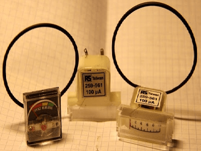
We have sorted out the nuances, now we move on to the third element of the circuit - this is the piezoelectric element. A piezo emitter (piezoelement) is necessary for auditory perception of the electromagnetic field; when this happens, the emitter makes a crackling sound. A piezoelectric element, or simply a “squeaker,” can be obtained from a non-working Tetris, Tamagotchi or watch. You can also replace the tweeter with a milliammeter from an old tape recorder. The milliammeter will show the level of the emitted field by deflecting the needle. If you decide to use a piezoelectric element and a milliammeter, the crackling noise produced will be a little quieter.
The circuit is powered by a voltage of 9 volts, so we will need a Krona battery. The circuit can be assembled on a printed circuit board or mounted. Wall-mounted installation for a simple circuit consisting of 5 elements would be preferable. Take cardboard, place the microcircuit with the legs down and pierce holes under each leg with a needle (14 pieces, 7 on each side). After preparing the place for the microcircuit, insert the legs into the holes made and bend them. This way we will securely fix the integrated circuit on the cardboard and make the work easier when soldering wires.


To avoid overheating the microcircuit, you should use a low-power soldering iron. Usually a 25 Watt soldering iron is used for soldering radio components. Let's start assembling the detector according to the diagram given in the article. If you have followed all the above recommendations, then the circuit should work instantly without any adjustments. Now we find a suitable case and integrate the circuit into it. Make holes under the tweeter and glue the piezo emitter on the back side. To prevent the detector from working constantly, solder a toggle switch into the power supply circuit break. Rebooting the detector by turning the toggle switch on and off will help you remove the microcircuit from self-excitation mode.


By tradition, I would like to end the article with a video report on the work done. The video tested the operation of a homemade and factory-made hidden wiring detector. As it turned out, the made detector more accurately showed the location of the electrical cable than a cheap purchased detector.
Having assembled a detector to search for hidden wiring, you should not be afraid of damage to the electrical network of your home, because you will always be able to find the electrical cable. Good luck in mastering simple circuits in radio electronics. If you have any questions, please contact me in the comments - we’ll sort it out!
About the author:
Greetings, dear readers! My name is Max. I am convinced that almost everything can be done at home with your own hands, I am sure that everyone can do it! In my free time I like to tinker and create something new for myself and my loved ones. You will learn about this and much more in my articles!
- " onclick="window.open(this.href," win2 return false > Print
There are ways to detect hidden wiring using “folk” methods, without special devices. For example, you can turn on a large load at the end of this wiring and search by compass deviation or using a coil of wire with a resistance of about 500 Ohms with an open magnetic circuit connected to the microphone input of any amplifier (music center, tape recorder, etc.), turning the volume to maximum. In the latter case, the wire in the wall will be detected by the sound of the 50 Hz pickup.
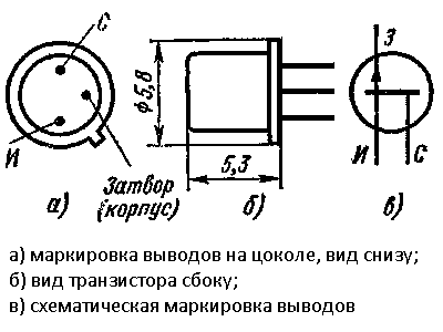
Device No. 1. It can be used to detect hidden electrical wiring, find a wire break in a bundle or cable, or identify a burnt-out lamp in an electric garland. This is the simplest device consisting of a field-effect transistor, a headphone and batteries. The schematic diagram of the device is shown in Fig. 1. The scheme was developed by V. Ognev from Perm.
Rice. 1. Schematic diagram of a simple finder
The principle of operation of the device is based on the property of the field-effect transistor channel to change its resistance under the influence of interference to the gate terminal. Transistor VT1 - KP103, KPZOZ with any letter index (in the latter, the housing terminal is connected to the gate terminal). The BF1 phone is a high-resistance phone, with a resistance of 1600-2200 Ohms. The polarity of connecting the GB1 battery does not matter.
When searching for hidden wiring, the housing of the transistor is moved along the wall and the maximum volume of sound with a frequency of 50 Hz (if it is electrical wiring) or radio transmissions (radio broadcast network) is used to determine the location of the wires.
The location of a broken wire in an unshielded cable (for example, the power cord of any electrical or radio device), or a burnt-out lamp of an electric garland is found in this way. All wires, including the broken one, are grounded, the other end of the broken wire is connected through a resistor with a resistance of 1-2 MOhm to the phase wire of the electrical network and, starting with the resistor, move the transistor along the bundle (garland) until the sound stops - this is the place where the wire breaks or a faulty lamp.
The indicator can be not only a headset, but also an ohmmeter (shown as dashed lines) or an avometer included in this operating mode. Power supply GB1 and telephone BF1 are not needed in this case.
Device No. 2. Now consider a device made with three transistors (see Fig. 2). A multivibrator is assembled on two bipolar transistors (VT1, VT3), and an electronic switch is assembled on a field-effect transistor (VT2).

Rice. 2. Schematic diagram of a three-transistor finder
The principle of operation of this finder, developed by A. Borisov, is based on the fact that an electric field is formed around an electric wire - this is what the finder picks up. If the SB1 switch button is pressed, but there is no electric field in the area of the WA1 antenna probe, or the finder is located far from the network wires, the VT2 transistor is open, the multivibrator does not work, and the HL1 LED is off.
It is enough to bring the antenna probe connected to the gate circuit of the field-effect transistor closer to the conductor with current or simply to the network wire, transistor VT2 will close, the shunting of the base circuit of transistor VT3 will stop and the multivibrator will start working.
The LED will start flashing. By moving the antenna probe near the wall, it is easy to trace the route of network wires in it.
The field-effect transistor can be any other from the series indicated in the diagram, and bipolar transistors can be any from the KT312, KT315 series. All resistors - MLT-0.125, oxide capacitors - K50-16 or other small ones, LED - any of the AL307 series, power source - Corundum battery or rechargeable battery with a voltage of 6-9 V, push-button switch SB1 - KM-1 or similar.
The body of the finder can be a plastic pencil case for storing school counting sticks. The board is mounted in its upper compartment, and the battery is placed in the lower compartment.
You can regulate the oscillation frequency of the multivibrator, and therefore the frequency of LED flashes, by selecting resistors R3, R5, or capacitors CI, C2. To do this, you need to temporarily disconnect the source output of the field-effect transistor from resistors R3 and R4 and close the switch contacts.
Device No. 3. The finder can also be assembled using a generator using bipolar transistors of different structures (Fig. 3). The field-effect transistor (VT2) still controls the operation of the generator when the antenna probe WA1 enters the electric field of the network wire. The antenna must be made of wire 80-100 mm long.

Rice. 3. Schematic diagram of a finder with a generator on
Transistors of various structures
Device No. 4. This device for detecting damage to hidden electrical wiring is powered from an autonomous source with a voltage of 9 V. The circuit diagram of the finder is shown in Fig. 4.

Rice. 4. Schematic diagram of a finder with five transistors
The principle of operation is as follows: one of the wires of the hidden electrical wiring is supplied with an alternating voltage of 12 V from a step-down transformer. The remaining wires are grounded. The finder turns on and moves parallel to the wall surface at a distance of 5-40 mm. In places where the wire is broken or terminated, the LED goes out. The finder can also be used to detect core faults in flexible cables and hose cables.
Device No. 5. Hidden wiring detector, shown in Fig. 5, already made on the K561LA7 chip. The scheme is presented by G. Zhidovkin.

Fig.5. Schematic diagram of a hidden wiring finder on the K561LA7 chip
Note.
Resistor R1 is needed to protect it from increased voltage of static electricity, but, as practice has shown, it does not need to be installed.
The antenna is a piece of ordinary copper wire of any thickness. The main thing is that it does not bend under its own weight, that is, it is rigid enough. The length of the antenna determines the sensitivity of the device. The most optimal value is 5-15 cm.
This device is very convenient for determining the location of a burnt-out lamp in a Christmas tree garland - the crackling noise stops near it. And when the antenna approaches the electrical wiring, the detector emits a characteristic crackling sound.
Device No. 6. In Fig. 6 shows a more complex finder, which, in addition to sound, also has a light indication. The resistance of resistor R1 must be at least 50 MOhm.

Rice. 6. Schematic diagram of a finder with sound and light indication
Device No. 7. Finder, the diagram of which is shown in Fig. 7, consists of two nodes:
♦ an AC voltage amplifier, based on the micropower operational amplifier DA1;
♦ an audio frequency oscillation generator assembled on an inverting Schmitt trigger DD1.1 of the K561TL1 microcircuit, a frequency-setting circuit R7C2 and a piezo emitter BF1.

Rice. 7. Schematic diagram of the finder on the K561TL1 chip
The principle of operation of the finder is as follows. When the WA1 antenna is located close to the current-carrying wire of the power supply network, the EMF pickup at a frequency of 50 Hz is amplified by the DA1 microcircuit, as a result of which the HL1 LED lights up. This same op-amp output voltage, pulsating at 50 Hz, drives the audio frequency oscillator.
The current consumed by the device microcircuits when powered from a 9 V source does not exceed 2 mA, and when the HL1 LED is turned on, it is 6-7 mA.
When the required electrical wiring is located high, it is difficult to observe the glow of the HL1 indicator and an audible alarm is sufficient. In this case, the LED can be turned off, which will increase the efficiency of the device. All fixed resistors are MLT-0.125, adjusted resistor R2 is SPZ-E8B type, capacitor CI is K50-6.
Note.
For a smoother adjustment of sensitivity, the resistance of resistor R2 should be reduced to 22 kOhm, and its lower terminal in the diagram should be connected to the common wire through a resistor with a resistance of 200 kOhm.
The WA1 antenna is a foil pad on a board measuring approximately 55x12 mm. The initial sensitivity of the device is set by trimming resistor R2. The faultlessly installed device, developed by S. Stakhov (Kazan), does not need adjustment.
Device No. 8. This universal indicator device combines two indicators, allowing you not only to identify hidden wiring, but also to detect any metal object located in the wall or floor (fittings, old wires, etc.). The finder circuit is shown in Fig. 8.

Rice. 8. Schematic diagram of a universal finder
The hidden wiring indicator is based on the DA2 micropower operational amplifier. When a wire connected to the input of the amplifier is located near the electrical wiring, a pickup frequency of 50 Hz is perceived by the WA2 antenna, amplified by a sensitive amplifier assembled on DA2, and switches the HL2 LED with this frequency.
The device consists of two independent devices:
♦ metal detector;
♦ hidden electrical wiring indicator.
Let's look at the operation of the device according to its schematic diagram. An RF generator is assembled on transistor VT1, which is put into excitation mode by adjusting the voltage based on VT1 using potentiometer R6. The RF voltage is rectified by the diode VD1 and moves the comparator assembled on the DA1 op-amp to a position in which the HL1 LED goes out and the periodic sound signal generator assembled on the DA1 chip is turned off.
By rotating the sensitivity regulator R6, the operating mode of VT1 is set at the generation threshold, which is controlled by turning off the HL1 LED and the periodic signal generator. When a metal object enters the inductance field L1/L2, the generation is interrupted, the comparator switches to a position in which the HL1 LED lights up. A periodic voltage with a frequency of about 1000 Hz with a period of about 0.2 s is applied to the piezoceramic emitter.
Resistor R2 is designed to set the lasing threshold mode at the middle position of potentiometer R6.
Advice.
The receiving antennas WA 7 and WA2 should be as far away from hand as possible and located in the head of the device. The part of the housing in which the antennas are located should not have an internal foil coating.
Device No. 9. Small-sized metal detector. A small-sized metal detector can detect nails, screws, and metal fittings hidden in walls at a distance of several centimeters.
Operating principle. The metal detector uses a traditional detection method based on the operation of two generators, the frequency of one of which changes as the device approaches a metal object. A distinctive feature of the design is the absence of homemade winding parts. The winding of an electromagnetic relay is used as an inductor.
The schematic diagram of the device is shown in Fig. 9, a.

Rice. 9. Small-sized metal detector: a - circuit diagram;
b - printed circuit board
The metal detector contains:
♦ LC generator on element DDL 1;
♦ RC generator based on elements DD2.1 and DD2.2;
♦ buffer stage on DD 1.2;
♦ mixer on DDI.3;
♦ voltage comparator on DD1.4, DD2.3;
♦ output stage on DD2.4.
This is how the device works. The frequency of the RC oscillator must be set close to the frequency of the LC oscillator. In this case, the output of the mixer will contain signals not only with the frequencies of both generators, but also with the difference frequency.
The R3C3 low-pass filter selects difference frequency signals that are fed to the input of the comparator. At its output, rectangular pulses of the same frequency are formed.
From the output of element DD2.4 they are supplied through capacitor C5 to connector XS1, into the socket of which a headphone plug with a resistance of about 100 Ohms is inserted.
The capacitor and the telephones form a differentiating chain, so clicks will be heard in the telephones with the appearance of each rising and falling pulse, i.e., with double the signal frequency. By changing the frequency of clicks, you can judge the appearance of metal objects near the device.
Element base. Instead of those indicated in the diagram, it is permissible to use the following microcircuits: K561LA7; K564LA7; K564LE5.
Polar capacitor - series K52, K53, others - K10-17, KLS. Variable resistor R1 - SP4, SPO, constant - MLT, S2-33. Connector - with contacts that close when the telephone plug is inserted into the socket.
The power source is a Krona, Corundum, Nika battery or a similar battery.
Preparing the coil. Coil L1 can be taken, for example, from an electromagnetic relay RES9, passport RS4.524.200 or RS4.524.201 with a winding resistance of about 500 Ohms. To do this, the relay needs to be disassembled and the moving elements with contacts removed.
Note.
The relay magnetic system contains two coils wound on separate magnetic circuits and connected in series.
The common terminals of the coils must be connected to capacitor C1, and the magnetic circuit, as well as the housing of the variable resistor, to the common wire of the metal detector.
Printed circuit board. The device parts, except for the connector, should be placed on a printed circuit board (Fig. 9, 6) made of double-sided fiberglass foil. One of its sides should be left metallized and connected to the common wire of the other side.
On the metallized side you need to attach the battery and the coil “extracted” from the relay.
The relay coil leads should be passed through the countersunk holes and connected to the corresponding printed conductors. The remaining parts are placed on the printing side.
Place the board in a case made of plastic or hard cardboard, and secure the connector to one of the walls.
Setting up a metal detector. Setting up the device should begin by setting the frequency of the LC generator within the range of 60-90 kHz by selecting capacitor C1.
Then you need to move the variable resistor slider to approximately the middle position and select capacitor C2 to make a sound signal appear in the phones. When moving the resistor slider in one direction or another, the frequency of the signal should change.
Note.
To detect metal objects with a variable resistor, you must first set the sound signal frequency as low as possible.
As you approach the object, the frequency will begin to change. Depending on the setting, above or below zero beats (equality of generator frequencies), or the type of metal, the frequency will change up or down.
Device No. 10. Indicator of metal objects.
When carrying out construction and repair work, it will be useful to have information about the presence and location of various metal objects (nails, pipes, fittings) in the wall, floor, etc. The device described in this section will help with this.
Detection parameters:
♦ large metal objects- 10 cm;
♦ pipe with a diameter of 15 mm - 8 cm;
♦ screw M5 x 25 - 4 cm;
♦ nut M5 - 3 cm;
♦ screw M2.5 x 10 -1.5 cm.
The operating principle of the metal detector is based on the property of metal objects to introduce attenuation into the frequency-setting LC circuit of a self-oscillator. The self-oscillator mode is set near the generation failure point, and the approach of metal objects (primarily ferromagnetic) to its contour significantly reduces the amplitude of oscillations or leads to generation failure.
If you indicate the presence or absence of generation, you can determine the location of these objects.
The schematic diagram of the device is shown in Fig. 10, a. It has sound and light indication of the detected object. An RF self-oscillator with inductive coupling is assembled on transistor VT1. The frequency-setting circuit L1C1 determines the generation frequency (about 100 kHz), and the coupling coil L2 provides the necessary conditions for self-stimulation. Resistors R1 (RUB) and R2 (SOFT) can set the operating modes of the generator.

Fig. 10. Metal object indicator:
A - schematic diagram; b - design of the inductor;
B - printed circuit board and placement of elements
A source follower is assembled on transistor VT2, a rectifier is assembled on diodes VD1, VD2, a current amplifier is assembled on transistors VT3, VT5, and a sound alarm is assembled on transistor VT4 and piezo emitter BF1.
In the absence of generation, the current flowing through resistor R4 opens transistors VT3 and VT5, so LED HL1 will light and the piezo emitter will emit a tone at the resonant frequency of the piezo emitter (2-3 kHz).
If the RF self-oscillator is working, then its signal from the output of the source follower is rectified, and the negative voltage from the rectifier output will close transistors VT3, VT5. The LED will go out and the jamming alarm will stop sounding.
When the circuit approaches a metal object, the amplitude of vibrations in it will decrease, or the generation will fail. In this case, the negative voltage at the detector output will decrease and current will begin to flow through transistors VT3, VT5.
The LED will light up and a beep will sound, indicating the presence of a metal object near the circuit.
Note.
With an audible alarm, the sensitivity of the device is higher, since it starts working at a current of a fraction of a milliampere, while a LED requires much more current.
Element base and recommended replacements. Instead of those indicated in the diagram, the device can use transistors KPZOSA (VT1), KPZZV, KPZZG, KPZOSE (VT2), KT315B, KT315D, KT312B, KT312V (VT3 - VT5) with a current transfer coefficient of at least 50.
LED - any with an operating current of up to 20 mA, diodes VD1, VD2 - any of the KD503, KD522 series.
Capacitors - KLS, K10-17 series, variable resistor - SP4, SPO, tuning - SPZ-19, constant - MLT, S2-33, R1-4.
The device is powered by a battery with a total voltage of 9 V. The current consumption is 3-4 mA when the LED is not lit and increases to approximately 20 mA when it is lit.
If the device is not used often, then switch SA1 can be omitted, supplying voltage to the device by connecting the battery.
Design of inductors. The design of the inductor coil of the self-oscillator is shown in Fig. 10, b - it is similar to the magnetic antenna of a radio receiver. Paper sleeves 2 (2-3 layers of thick paper) are put on a round rod 1 made of ferrite with a diameter of 8-10 mm and a permeability of 400-600; coils L1 (60 turns) and L2 ( 20 turns) - 3.
Note.
In this case, winding must be carried out in one direction and the terminals of the coils must be correctly connected to the self-oscillator
In addition, coil L2 should move along the rod with little friction. The winding on the paper sleeve can be secured with tape.
Printed circuit board. Most of the parts are placed on a printed circuit board (Fig. 10, c) made of double-sided foil fiberglass. The second side is left metallized and is used as a common wire.
The piezo emitter is located on the back side of the board, but it must be isolated from metallization using electrical tape or tape.
The board and battery should be placed in a plastic case, and the coil should be installed as close to the side wall as possible.
Advice.
To increase the sensitivity of the device, the board and battery must be placed at a distance of several centimeters from the coil.
Maximum sensitivity will be on the side of the rod on which coil L1 is wound. It is more convenient to detect small metal objects from the end of the coil; this will allow you to more accurately determine their location.
♦ step 1 - select resistor R4 (to do this, temporarily unsolder one of the terminals of the diode VD2 and install resistor R4 of such a maximum possible resistance so that there is a voltage of 0.8-1 V at the collector of transistor VT5, while the LED should light up and the sound signal should sound.
♦ step 2 - set the resistor R3 slider to the bottom position according to the diagram and solder the VD2 diode, and unsolder the L2 coil, after which the transistors VT3, VT5 should close (the LED will go out);
♦ step 3 - carefully moving the slider of resistor R3 up the circuit, ensure that transistors VT3, VT5 open and the alarm turns on;
♦ step 4 - set the sliders of resistors Rl, R2 to the middle position and solder coil L2.
Note.
When L2 approaches close to L1, generation should occur and the alarm should turn off.
♦ step 5 - remove coil L2 from L1 and achieve the moment the generation fails, and use resistor R1 to restore it.
Advice.
When tuning, you should strive to ensure that coil L2 is removed to the maximum distance, and resistor R2 can be used to disrupt and restore generation.
♦ step 6 - set the generator to the brink of failure and check the sensitivity of the device.
At this point, setting up the metal detector is considered complete.