It is possible to install an electricity meter yourself; it is not necessary to call a certified specialist. It is enough to know and be able to safely carry out work with electricity, follow instructions correctly and understand what the danger of electric shock is. However, before installation, you must obtain permits, and to directly connect to the network, you will need to call a representative of the energy supply company. We will now talk about all the points in more detail, having looked at how to install an electric meter with your own hands in a private house and apartment.
Organizational events
Technical events
Having the technical documentation in hand, indicating the names and location of installation, you can begin installing the electric meter yourself. First of all, you need to purchase materials and elements for self-assembly.
If the electricity meter is planned to be installed on the street (for private houses and dachas this is optimal place placement), on external wall at home (facade) or on a pole, it is necessary to install YUR-NG (external metering and distribution box, sealed box). It is already equipped with a place and elements for attaching the metering device, as well as a separate lockable box for input. In addition, the box is equipped for the installation of modular machines. You can see an example of installing an electric meter in an outdoor box in the photo:

In order to install an electric meter indoors, you can use a YUR box for internal installation or a mounting board; it also provides space for installing additional machines.

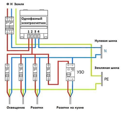
Described in our article. It is better to move or replace a meter, as well as install a new meter, from one to a new one. In addition, it is recommended to install protection elements (RCDs, automatic devices) in the panel instead of outdated plugs, having previously laid down the possibility of switching to modern system electricity supply You can read about that in our article. The figure below shows a connection diagram for a single-phase electric meter with grounding:
If you decide to install an electric meter yourself, according to the rules of the PUE (see), you need to fulfill the following requirements:
- The electricity meter can be installed in electrical cabinets, on switchboards and panels with a rigid structure.
- The installation height at the electric meter terminals varies from 0.8 meters to 1.7 meters.
- In places where there is a risk of damage, contamination, or access by unauthorized persons, the electric meter must be installed in a box and locked with a key.
- The location of the meter should allow easy access for maintenance, reading, and replacement.
- The input cable must meet the design requirements and be of appropriate cross-section for trouble-free supply.
- Twisting and soldering on the input cable are not allowed; it must be one solid piece from the access input to the metering device.
When connecting the cable to the meter, know that the core must be like this, according to the accepted rules - brown, black, red, white are conductors connected to the phases, designated as L. Blue - zero wire N, yellow-green insulation for the protective conductor PE. Keeping color coding in mind makes it difficult to get confused.
Please note that installing an electric meter under voltage is strictly prohibited! All electrical installation work must be carried out only with the input circuit breaker turned off!
In a private home, as well as in summer cottage, in the event that the newly installed electric meter is located on a post at the border of the site, it is possible to connect the house from the nuclear power supply system by laying it, or by doing it at a height by air. We recommend that you read these articles on our resource, which describe in detail methods for laying cables in a trench and self-production cable wiring.
By the way, the cost of installing an electric meter by a specialist varies from 1000 rubles for a single-phase model and from 1500 rubles for a three-phase device.
Installation of a single-phase model
As for the methods of connecting devices, as well as, we have discussed in detail in the relevant articles, which we strongly recommend that you read. Otherwise, we hope that you liked our information about how to install an electric meter yourself and what documents are needed for this.
Installation of a single-phase model
Rules for installing a three-phase meter
To control and account for consumed electrical energy, you need a special device - an electric meter. Both in large industrial enterprises and in private apartments, when concluding an agreement for the supply of electricity, this device cannot be avoided.
When installing a meter to calculate consumed electricity, you must correctly connect it to the power supply circuit.
Electricity meters can be either single-phase or three-phase, with direct or indirect connection.
In this article we will tell you in detail how to independently connect both types of electricity meters.
How to install a single-phase electric meter
A single-phase electric meter is connected directly to the power line break. Before installing the meter, no electricity consumers should be connected to the power line. To protect the power supply line in front of the meter, it is advisable to install an input circuit breaker. It will be necessary when replacing the meter, so as not to de-energize the entire supply line.
It is also necessary to install a circuit breaker after the meter; it will protect the outgoing line and the meter itself if a malfunction occurs in the electricity consumer circuit.
When connecting an electric meter, you need to pay attention to the connection diagram; it is usually located on the back of the terminal cover. A single-phase meter has four terminals for connecting wires:
- Phase wire input.
- Phase wire output.
- Neutral wire input.
- Neutral wire output.

The power wires after the input circuit breaker are stripped of insulation by 15 mm and connected to terminals 1 and 3, the outlet wires are also stripped of insulation and connected to terminals 2 and 4, according to the diagram on the cover of the device.

This electric meter connection diagram is suitable for an apartment in a multi-storey building, a garage, country house or for a small shopping pavilion.
Connecting a modern electronic meter of the Micron type is no different from the above diagram, which can be used to install any single-phase metering device.
Video: connecting a single-phase single-tariff electricity meter
We connect a three-phase electric meter
There are two types of connection of a three-phase meter, direct and indirect, through isolating current transformers.
If it is necessary to take into account the consumption of a relatively small number of three-phase low-power consumers, then the electricity meter is installed directly into the gap in the supply wires.
If it is necessary to control sufficiently powerful consumers of a three-phase electrical network, and their currents exceed the rated value of the electric meter, then it is necessary to install additional current transformers.
For a private country house, or small production, it will be enough to install only one meter, designed for a maximum current of up to 50 amperes. Its connection is similar to that described above for a single-phase meter, but the difference is that when connecting a three-phase meter, a three-phase power supply is used. Accordingly, the number of wires and terminals on the meter will be greater.

Consider direct connection of the meter
The supply wires are stripped of insulation and connected to a three-phase circuit breaker. After the machine, three phase wires are connected to the 2, 4, 6 terminals of the electric meter, respectively. The output of phase wires is carried out to 1; 3; 5 terminals. Input Neutral wire is connected to terminal 7. Output to terminal 8.
After the meter, for protection, automatic switches are installed. For three-phase consumers, three-pole circuit breakers are installed.
More conventional, single-phase electrical appliances can also be connected to such a meter. To do this, you need to connect a single-pole circuit breaker from any outgoing phase of the meter, and take the second wire from the neutral grounding bus.
If you plan to install several groups of single-phase consumers, they must be evenly distributed by powering the circuit breakers from different phases after the meter.

Indirect connection of the meter through current transformers
If the consumed load of all electrical appliances exceeds the rated current value that can pass through the meter, it is necessary to additionally install current isolating transformers.
Such transformers are installed in the gap of power current-carrying wires.
The current transformer has two windings, the primary winding is made in the form of a powerful bus threaded through the middle of the transformer; it is connected to the break in the power wires supplying electrical consumers. The secondary winding has a large number of turns of thin wire; this winding is connected to the electric meter.
This connection is significantly different from the previous one; it is much more complex and requires special skills. We recommend inviting a qualified specialist to work on connecting a three-phase meter with current transformers. But if you are confident in your abilities and have similar experience, then this is a solvable task.
It is necessary to connect three current transformers, each for its own phase. Current transformers are mounted on back wall introductory cabinet study. Their primary windings are connected after the input switch and a group of protective fuses, into the break of the phase power wires. A three-phase electric meter is installed in the same cabinet.
The connection is made according to the approved diagram.
A wire with a cross section of 1.5 mm² is connected to the power wire of phase A, before the installed current transformer, its second end is connected to the 2nd terminal of the meter. Similarly, connect wires with a cross-section of 1.5 mm² to the remaining phases B and C; on the meter they go to terminals 5 and 8, respectively.
From the terminals of the secondary winding of the current transformer, phase A, wires with a cross section of 1.5 mm² go to the meter at terminals 1 and 3. The phasing of the winding connection must be observed, otherwise the meter readings will be incorrect. The secondary windings of transformers B and C are connected in a similar way; they are connected to the meter at terminals 4, 6 and 7, 9, respectively.
The 10th terminal of the electric meter is connected to the common neutral grounding bus.
Do-it-yourself installation of a meter in a panel on a landing or in a garage
On each landing of a multi-storey residential building, there is a metering panel with electricity meters that calculate electricity consumption on the entire floor. What is needed to install the meter in the distribution board:
- Prepare necessary tools: wire cutters, pliers, wire strippers, screwdrivers, electrical tape, etc.
- Access to the input switch to disconnect the line of this floor from the network.
Connection diagram for the meter and circuit breakers.

First you need to make branches from the supply line. To do this, the previously de-energized main wires are stripped of insulation using special pliers to a distance of 3 cm. A special terminal block for branching the wire is placed in this place. After installing the terminal block on the main wire, the outlet wire is connected to it, which will go to the input circuit breaker.
A branch is made from the neutral main wire in a similar way.
Then they install all the protection devices, and the meter itself, on the switchboard panel; this is more convenient to do using a Din-rail. After installing all components in place, the wires are connected.
The made branch from the phase main wire is connected to the input circuit breaker, then from the output of the input circuit breaker the wire is connected, according to the diagram, to the first terminal of the meter. The branched neutral wire is connected directly to the second terminal of the meter; a circuit breaker is not needed for it.
From the third terminal the wire goes to group consumer protection circuit breakers. The wire from the fourth terminal is connected to the common grounding bus, and all neutral wires from consumers will be connected to it.
The phase wires coming from the apartment are connected to the lower terminals of the circuit breakers, which are installed after the meter. For each phase wire (group of electrical appliances) it is necessary to install a separate circuit breaker. It is prohibited to connect several phase wires to one machine.
All neutral wires from groups of electricity consumers in the apartment are connected to a common neutral bus.
Remember that the panel on the staircase contains not only your meters and circuit breakers, but also those of your neighbors. To avoid confusion if any faults occur, be sure to mark your circuit breakers and meter with the apartment number.
Installing an electricity meter for a garage is similar. The only difference is that there is no need for a branch of the main wires, since ready-made separate power wires are brought into the garage.
Commissioning or reconstruction of electrical wiring in a house or apartment is rarely complete without installing or replacing an electric meter. According to the standards, work can only be performed by specially trained people who have permission to work in networks with voltages up to 1000 V. But you can install all the elements and connect the meter to the load (electrical appliances) without connecting the power supply yourself. Afterwards, you need to call a representative of the energy supply organization to test, seal and start up the system.
Connecting a meter: rules and basic requirements
Exactly all the requirements are specified in the PUE, and the basic rules are as follows:
- Must be installed with protection from weather conditions. Traditionally they are mounted in special boxes (boxes) made of non-flammable plastic. For outdoor installation, the boxes must be sealed and must provide the ability to control readings (have glass opposite the display).
- Fixed at a height of 0.8-1.7 m.
- The meter is connected using copper wires with a cross-section corresponding to the maximum current load (available in the technical specifications). The minimum cross-section for connecting an apartment electric meter is 2.5 mm 2 (for a single-phase network this is a current of 25 A, which is very low today).
- The conductors are insulated, without twists or branches.
- With a single-phase network, the state verification date of the meter is no older than 2 years, with a three-phase network - one year.
Installation location of the meter in apartment buildings regulated by the project. The meter can be installed on a landing or in an apartment - in. If placed in an apartment, it is usually not far from the door.

There are also several options in a private house. If the pole is in the yard, you can place the meter on the pole, but it’s better to place it indoors. If, according to the requirements of the energy supply organization, it must be located on the street, they place it on the front side of the house in a sealed box. The machines going to groups of consumers (various devices) are mounted in another box in the room. Also, one of the requirements when installing electrical wiring in a private house: the wires must be visually inspected.

In order to be able to carry out work on the electric meter, an input switch or machine is installed in front of it. It is also sealed, but there is no way to put a seal on the device itself, like on a meter. It is necessary to provide for the possibility of separate sealing of this device - buy a small box and mount it inside the apartment panel or place it separately on the landing. When connecting a meter in a private house, the options are the same: in the same box with the meter on the street (the entire box is sealed), in a separate box next to it.
Connection diagram for a single-phase electric meter
Meters for a 220 V network can be mechanical and electronic. They are also divided into single-tariff and two-tariff. Let us say right away that connecting any type of meter, including two-tariff ones, is carried out according to the same scheme. The whole difference is in the “filling”, which is not available to the consumer.
If you get to the terminal plate of any single-phase meter, you will see four contacts. The connection diagram is indicated on the back of the terminal block cover, and in a graphical representation everything looks like in the photo below.

If you decipher the diagram, you get the following connection order:

The meter is connected with wires stripped to 1.7-2 cm. The specific figure is indicated in the accompanying document. If the wire is stranded, lugs are installed at its ends, which are selected according to thickness and rated current. They are crimped with pliers (can be clamped with pliers).
When connecting, the bare conductor is inserted all the way into the socket, which is located under contact pad. In this case, it is necessary to ensure that no insulation gets under the clamp, and also that the cleaned wire does not stick out from the housing. That is, the length of the stripped conductor must be maintained exactly.
The wire is fixed in old models with one screw, in new ones - with two. If there are two mounting screws, tighten the one on the far side first. Tug the wire slightly to make sure it is secure, then tighten the second screw. After 10-15 minutes the contact is tightened: copper is a soft metal and is pressed down a little.
This applies to connecting wires to a single-phase meter. Now about the connection diagram. As already mentioned, an input machine is placed in front of the electric meter. Its rating is equal to the maximum load current; it is triggered when it is exceeded, excluding equipment damage. Afterwards they install an RCD, which is triggered when the insulation breaks down or if someone touches live wires. The diagram is shown in the photo below.

The circuit is not difficult to understand: from the input, zero and phase go to the input of the circuit breaker. From its output they go to the meter, and from the corresponding output terminals (2 and 4) they go to the RCD, from the output of which the phase is supplied to the load breakers, and the zero (neutral) goes to the zero bus.
Please note that the input circuit breaker and the input RCD are two-contact (two wires enter) so that both circuits open - phase and zero (neutral). If you look at the diagram, you will see that the load breakers are single-pole (only one wire goes to them), and the neutral is supplied directly from the bus.
Watch the meter connection in video format. The model is mechanical, but the process of connecting the wires is no different.
There are three phases in a 380 V network, and electric meters of this type differ only in the large number of contacts. The inputs and outputs of each phase and neutral are located in pairs (see the diagram). Phase A enters the first contact, its output is on the second, phase B is the input on the 3rd, its output on the 4th, etc.

The rules and procedure are the same, only there are more wires. First we clean it, align it, insert it into the contact connector and tighten it.
The connection diagram for a 3-phase meter with a consumption current of up to 100 A is almost the same: input machine-meter-RCD. The only difference is in the distribution of phases to consumers: there are single- and three-phase branches.

Connecting a single-phase electric meter, from a technical point of view, is not difficult. Some skills and a minimum set of tools are enough. More importantly, the electric meter, like any other metering device, must meet certain requirements, otherwise the grid company inspector will refuse to register it. In addition, representatives of energy supply organizations have their own opinion about some technical specifications, different from the consumer's opinion. It is precisely these moments that are discussed in this article.
Requirements for electric meters
There are several mandatory requirements, without which the meter will not be registered.
- Each meter must have a passport that records: a conclusion about the suitability of the device, the date of initial and subsequent verification, information about commissioning. The passport is stored for the entire period of operation of the device.
- The device must be included in the State Register of Measuring Instruments and have certificates of type approval and conformity.
- Have government certification seals on the casing fastening screws, and a seal from the energy supply organization on the clamping cover of the terminal block.
- The age of state verification seals at the time of installation should be no more than 12 months for three-phase meters, and for single-phase 24.
- The accuracy class of a newly installed meter for metering electricity consumed by citizens must be no lower than 2.0 (RF PP No. 442, clause 138).
- The placement rules are set out in the PES clauses 1. 5. 27. – 1. 5. 38. They do not contain any special requirements, except for the only one, ensuring free and convenient access.
If the listed rules are met, i.e., all the conditions stipulated by the legislation of the Russian Federation are met, then the refusal of the network company to put the electric meter into operation on the basis that the meter is of the wrong brand, model, manufacturer is illegal (RF PP No. 442, clause 148).
Connection diagram for a single-phase electric meter
It’s hard to make a mistake here; the connection diagram for each specific model is shown on the terminal block cover and in the passport.
 Single-phase direct-connection electricity meters use a sequential connection scheme. From left to right. 1 – supply wire phase, 2 – load phase wire, 3 – supply wire neutral, 4 – load zero wire. Wires stripped of insulation (25-30 mm) are inserted into contact clamps and securely clamped with screws. That's actually the whole installation.
 The power part of the circuit is typical, i.e. it is suitable for connecting any single-phase direct-connection electric meter, regardless of its brand, model and manufacturer. All you need to know before proceeding with installation is the purpose of each of the incoming conductors.
In theory, the color marking of the wires should serve as an indicator of wire ownership. Neutral (zero), wire insulation color blue, blue, blue with a white stripe. Zero protective (grounding), insulation color is yellow with 1-2 bright green stripes. Phase, insulation color: black, red, brown.
Even if the color of the wire insulation is different, I do not recommend relying on it 100%. In practice, color marking can only serve as a guide to determine the identity of the conductor. You can reliably verify the identity of the phase wire using a probe indicator. It is more difficult to distinguish between the neutral and ground wires. Depending on the circumstances, you can use one of the methods shown in.
Actually, connecting an electric meter to the power grid is not difficult. More often, questions arise related to network design and operational features. I will answer some of them.
Is it possible to connect an electric meter without an input switch?
 In principle, the input switching device can be of any design. The only mandatory requirement is that it must be designed for a fairly high current, from 30-40 A.
 In the PES paragraph 1. 5. 36. there is a direct answer, no, it is impossible. The purpose of the switching device (fuse, input circuit breaker, switch) in this case is precisely for the safe installation and replacement of the electric meter. Contrary to popular belief, the input switch does not have to be located in close proximity to the electric meter. It is quite possible that the input switching device will be located in the interfloor distribution board. This does not contradict the rules if the distance between the meter and the switch does not exceed 10 meters.
Is it possible to install an electric meter on the street?
If you strictly follow the PEU, then you can’t step 1. 5. 27. The threshold for the lower temperature is specified, not lower than 0°. Considering the harsh climate of our country, maintaining the required temperature, even in a closed box heated by an incandescent light bulb, is impossible in principle. Nevertheless, energy supply organizations considered this installation method the most acceptable. Time will show the correctness of this approach, but in any case we will wait for changes.
Does the electric meter need grounding?
No, it is not necessary, but if such a question arises, I very much suspect that there is an intention to use the contact clamp as the splitting point of the combined PEN conductor (TN-C system). Alternatively, connect the output neutral wire to the ground loop. I strongly advise you not to conduct such experiments. This won't end well. Read about the features of various grounding systems on one website.
If everything is clear with the power part, then the connection to the ASKUE metering system is different. Depending on the communication system, the device must have certain functions. ASKUE assumes the same type of technical accounting means, therefore, before buying a specific model, you need to know for sure how data is transferred in a specific, local system.
 The difference between this circuit and similar ones is the absence of an input RCD. I think it is wrong to place this device at the entrance for all occasions. The only small plus from connecting a common RCD is a small saving of money, but the big minus is the impossibility of localizing the fault.
  The previous scheme brought to reality. 1 – input switch, 2 – N bus, 3 – PE bus, 4 – group circuit breakers and automatic circuit breakers.
 Characteristics of electricity meters
Although it is dedicated to the choice of parameters, when talking about how to connect an electric meter one cannot help but touch upon this topic once again. This time, from the point of view of the efficiency of electricity metering. Believe me, this knowledge will help in case of lack of mutual understanding with representatives of regulatory authorities.
- Number of phases. In our case, one. Therefore, we will only talk about direct-on meters that read the total (absolute) power consumption.
- Established operating voltage range. Indicates the voltage limits within which the device operates with the stated accuracy. Sometimes this parameter is confused with the maximum voltage, i.e. power surges, dips, after exiting which the electric meter saves the previously recorded information. The lower limit voltage value is zero (no voltage), and the upper value is the highest value of the extended operating voltage range. Another parameter within which the device remains operational, but its measurement error does not correspond to the declared accuracy class.
- Rated and maximum current. In the passport, the rated (base) current is indicated first, and the maximum current value is indicated in parentheses or separated by a hyphen. For example, so 5-60 or so 10 (100). If with maximum current everything is clear, for an apartment 60 A is more than enough, and no one in their right mind would put more than 100 A on one phase, then the minimum value of the base current can cause problems when registering the device.
The sensitivity threshold (starting current) depends on the rated current. Thus, for a single-phase meter with an accuracy class of 2.0, the starting current should not exceed 0.46% of the rated current, and for an accuracy class of 1.0, the sensitivity threshold is even lower than 0.4%. In fact, this percentage varies slightly among different models. Network companies attach great importance to this seemingly insignificant difference.
Let me explain using the example of Mercury 230AM-01 and 230AM-02 devices. The first has a base current of 5 A, the second 10. Although both devices have the same accuracy class of 1.0, their sensitivity is different: 20 and 25 mA, respectively. From the point of view of the inspecting authorities, using the 230AM-02 device instead of the more sensitive 230AM-01, there is a hypothetical possibility of not taking into account about 10 kW per year. That’s right, there is some truth in these fabrications, but this is provided that the power of the constantly connected load during the year does not exceed 1.1 W.
- Accuracy class. Although, according to the law, the accuracy class cannot be lower than 2.0, this does not mean that meters with a lower accuracy class at the time of the adoption of Russian Government Decree No. 442 (05/04/2012) immediately became illegal. Paragraph 142 of the same document contains an explanation that devices used at the time the Resolution entered into force can be used until the end of their service life.
 If there is only one current circuit, then there is one circle on the stick of the graphic icon.
 - Number of measuring elements in the current circuit. For normal operation of a single-phase electric meter, one coil (sensor) connected in series to the phase circuit is sufficient, but to prevent the known reception and phase transfer, modern electronic meters use two current measuring circuits, one in phase and one in zero. Readings are taken from the circuit where the current is greater.
 It’s not visible in the picture, but in fact the device shows the current strength in the circuit: the body is connected, but not working washing machine– potential equalization system. The current strength may not be impressive, but there is no load as such. It’s just that this simple picture illustrates the fact that there are currents in the N and PE circuits and an incorrectly connected electric meter, with a measuring element in the zero circuit, will take them into account, even if there is no current in the phase current coil.
 It would seem that to us honest consumers, it makes no difference whether the meter can take into account the current of the neutral conductor or not. After all, when turned on correctly, the current strength in both conductors is equal, but if you intentionally or unknowingly connect the neutral wire coming from the meter to a common neutral bus located in the interfloor distribution board, then the meter will count non-stop, taking into account the energy consumed by you, your neighbors and others God knows by whom.
Few will remember the time when electricity bills were calculated based on the number of lighting fixtures in the house, which, naturally, did not make it possible to accurately determine the amount of energy consumed.
Today, such a method is, of course, unacceptable, since there are many modern metering devices with a high accuracy class.
If you plan to connect a new meter yourself, and you need simple circuit connecting it, then carefully studying this article will help you avoid difficulties during the installation process.
Primary requirements
So, before connecting the electric meter, you need to agree on the following details with the energy supply organization:
Since not everyone knows how to connect an electric meter correctly, many make mistakes during installation, although there is nothing complicated here.
Let's take a closer look at how to connect an electric meter and machines:
- to protect the measuring device from overvoltage in the network, automatic machines are installed before entering the line into the meter;
- if the machines are installed after commissioning, if there are significant voltage fluctuations, the device will simply fail;
- According to regulatory documentation, only one circuit breaker is allowed to be installed per phase wire, but if possible, it is preferable to install a two-pole one, which will cut off both the supply and the neutral.
The machines are mounted on a DIN rail, and it must be grounded on the body of the electrical panel, if it is not a component of it.
Single phase electricity meter
A single-phase electric meter is designed as follows - all consumers of electrical energy in the house are powered from one wire (phase). A single-phase device has four terminals through which electricity is supplied to the premises, as well as communication with the general electrical network.
Connecting a single-phase meter
Let's consider step by step how to connect a single-phase electric meter:
- First of all, it is necessary to de-energize the room, and then remove the old meter.
- The new device is fixed in a previously prepared place.
- The phase wire is connected to terminal No. 1. As a rule, it is red, but if you have any doubts, you can test it with an indicator screwdriver - the indicator on the phase wire should light up.
- The phase wire from the apartment network is connected to terminal No. 2. Thus, the first circuit is ready.
- In a similar way, the neutral wire from the apartment and public networks is connected to terminals No. 3, 4.
Before connecting the electric meter, familiarize yourself with its connection diagram.

Connecting a three-phase meter
In this case, consumers of electrical energy are divided into groups, which is considered safer.
It is somewhat more difficult to connect a three-phase meter, but the principle is still the same. This controller has 8 terminals. Let's consider step by step instructions how to connect a three-phase electric meter:

Electric meter "Mercury 201"
Before connecting the Mercury electric meter, it is advisable to consider it design features. The metering device is made in a plastic rectangular case. There is an LCD display on the front panel of the electric meter. On the right side there is a “plate” with the main characteristics. The metering device is characterized by compact overall dimensions and light weight.

The lower removable panel of the meter protects the device contacts. The cable is connected to these contacts using a screw connection.
Connection diagram for the Mercury meter
The Mercury meter is connected in the same way as any electrical energy meter. The main requirement is the choice of output and input conductors. The input input will be as determined by the utility company. In this case, any wires can be used as output conductors.
The connection diagram for the metering device is as follows:

How to connect the Mercury 201 electricity meter: step-by-step instructions

Now you know how to properly connect an electric meter, but do not forget that self-replacement devices without the consent of the company that supplies electrical energy is strictly prohibited. Without permitting documentation for the installation of new equipment, the old electric meter is also prohibited from being removed.