Currently, everyone can build a frame house with their own hands, for seasonal or permanent residence. All frame houses are a complex technical constructor for adults, and they are assembled only if the instructions are followed.
This document for  arch houses is their drawing. And this is not only an official document, but also a guarantee that the frame house you have chosen fully complies with all technical standards and quality standards, as well as adapted to your regional climatic conditions.
These documents, which describe in detail the assembly and installation of the house, must be drawn up at the stage of commencement of construction. Also, the cost of a frame house is listed in the estimate, which clearly takes into account all the building materials that are needed to assemble the house.
Complete set of documentation and drawings of houses
Blueprints frame houses- This is a large and voluminous document, which contains about 100 pages, which contains a detailed plan, diagrams and detailed instructions for assembly and installation.
 Conventionally, all documents can be divided into three main parts, which will make the instructions easier and more convenient to use.
This instruction is read by both professionals and novice builders who do not have any education and experience in assembling houses. But for a better installation, you need at least a little understanding of the documentation. The attached documents contain a specification, a clear sequence of construction work, exact production dates, and other important information.
Also in the documentation it is written in detail how to perform vapor barrier and wind protection, GOSTs and SNiP are indicated in force in different situations, the principle of choosing window and door openings is indicated. There are also general recommendations for the installation of a single-story.
Detailed guide to the construction of different types of foundation
![]() In this guide you will find a working drawing of a frame house, which will be necessary for the construction of the foundation.
In this guide you will find a working drawing of a frame house, which will be necessary for the construction of the foundation.
Detailed instructions for installing and pouring the foundation contain not only the dimensions and depth of the foundation, but also important information on the correct setting of the foundation formwork with minimal time and low costs.
Also, the documentation for installing the foundation will include the calculation of reinforcement, its type and assembly scheme. Data on fastening the lower trim to the foundation will be indicated.
The largest part of the documents is this instruction. It includes information on assembling the main part of the house.
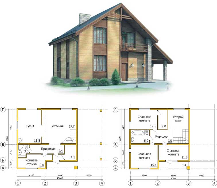
All drawings of a frame country house are schemes for attaching and assembling rafters, installing support boards, and fitting the top trim of the house. If this is a frame house of a one-story type with an attic, then detailed instructions for arranging an attic room are also attached. And also there is documentation on the correct setting of frame walls, assembly of corner structures, installation of internal load-bearing and decorative partitions.
A detailed wall layout plan is also attached, and it indicates the typical design of the entire space of the house, or a design project for the interior of the house and its layout, previously agreed with the customer.
Also included in the project documentation. The general design of the house is provided, a special version of the roof, fences and lifts has been developed. During the construction and installation of country houses or 6x9, all working documentation must be completed with all the necessary details and elements, and window structures.
For buildings of a seasonal nature, double-glazed windows with single glass are most often used to reduce the cost of the entire structure, and for year-round houses, two-chamber plastic windows are used.
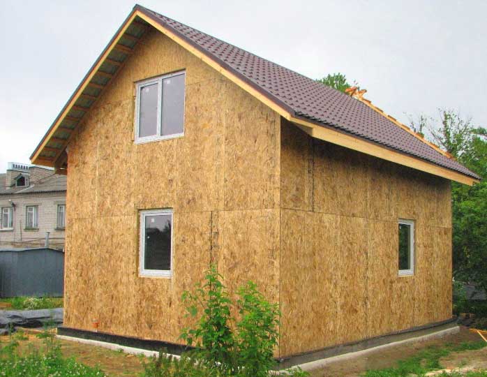
With this scheme, it is possible. A standard frame house is assembled on site, its base- this is a frame made of timber, separately supplied, and which is sewn up after the assembly of the main frame is completed. The technological process of assembling a panel house will be slightly different. The main beacons are placed on the foundation and fasteners and parts are mounted. And the shields themselves are wall elements, they are assembled on a horizontal surface, and after that they are installed on the foundation.
Depending on the complexity of the project, the thickness of the walls is also selected, as a rule, up to 270 mm. This will provide the necessary thermal insulation level and will not allow empty waste of material. The insulation is usually mineral wool, and for interior decoration it is drywall. The roof is covered with metal tiles. But it is also worth noting that any standard projects of frame houses with 6x8 drawings can be changed at the request of the customer.
Detailed guide for laying and installation of all utilities
 The gas pipeline, electrical network, sewerage, water supply are the main parts of a modern frame house. Not only the comfortable use of this object, but also the reliability and quality of the entire structure will depend on the correctness of the work on their installation and installation.
In this section of the manual, you can find out how many switches and sockets you need, where it is better to place them for the safer functioning of the frame house.
These principles will also apply to plumbing, ventilation and sewerage. Qualitatively drawn up projects of frame houses include all communication interchanges and routes. The procedure for laying engineering networks and their connection are present in the documents for the installation and installation of engineering networks.
Estimate for the construction of a frame house
The biggest danger when starting the construction of a one-story frame house is the incorrect calculation of the entire construction budget and not taking into account all the necessary building materials. In the most ideal case, the process may drag on indefinitely, and in the worst case scenario, the project may be frozen and work will be suspended.
To avoid this situation during the independent construction of a frame house, you need to order project documentation from specialists.
 Free drawings of one-story frame houses and their schemes also include a special detailed estimate. Which indicates how much building material is needed at each stage of construction in rolls, meters, kilograms, and also indicates a specific range of market prices.
If you are building a house in stages, then you will not need to spend money immediately on the purchase of all building materials. You can buy them gradually, as the phased construction of the house.
It is quite convenient in terms of storage, delivery and unloading. This issue is especially relevant for builders of houses in garden plots. In a small space, it will be almost impossible to install a house, arrange all building materials, and protect them from external precipitation.
Nice free project
A good one is working drawings, detailed plans and diagrams that are necessary for each of the stages of building a frame house.
After viewing this type of document, you will not have any questions about building a house. High-quality and understandable project documentation is a wide opportunity to plan all the work at the construction site and minimize all errors.
In addition, a good and high-quality design optimizes the work of builders, minimizes sawing and material adjustment, and this leads to significant time savings on the construction site.
 And you can also avoid unplanned waste left after sawing the building material, and this will lead to tangible savings. This can be done by selecting special materials for a specific project, or by developing a frame house project, taking into account the materials currently on the market. Sheet material that is a multiple of the area of the walls makes it possible to make the sheathing very quickly and without any unnecessary waste.
A good and high-quality project can reduce costs in another way. For example, the project provides for the use of lumber for formwork in future construction, and this leads to a significant reduction in costs and large savings.
One-story frame house: free projects and drawings
Free projects is a certain myth that is widespread among builders.
 Downloading or finding a ready-made project that would completely satisfy you is simply not realistic. There are hundreds of free drawings of some parts of the house on the Internet, different layouts and models of one-story frame houses, and options for decorating the facade. But there are no high-quality and reliable projects in the network.
This is due not only to copyright infringement, but also to the fact that all finished projects of frame houses and drawings are complex documentation that has been developed for certain building conditions. This document takes into account the type of soil and the level of groundwater, their heaving, and these indicators help to choose the right foundation and calculate the bearing load.
 Even the same type of one-story frame houses, identical at first glance, have differences that are specifically reflected in the project documentation. In each specific case, different building materials, different amounts of insulation layer, different interlocks and roofing are used. Even engineering communications in the same frame houses located in different regions can be arranged differently.
Free projects on the Internet can be found for small country houses from the old years of construction. Although, with the advent of the latest technologies and building materials, as well as simpler technical solutions, they will not be the right document.
Without documents and drawings, the construction of a frame house will be 25% more expensive than with documents.
As a rule, the cost of a turnkey package of documents for an average frame house will cost about 10 thousand rubles. On average, the cost of a finished project does not exceed 5% of the cost of all work, and more often it is 2%. Moreover, the availability of high-quality documentation will allow you to save a large part of the budget.
When make up floor plans, then the names of the rooms must indicate them. You can do this in the following ways:
Bring them in the table (explication) of the premises
Indicate them directly on the drawings
In the second case, the room numbers must be put in circles. If the purpose of a particular room is clear and without specifying the name, then it is not applied to the drawing. Most often, this is done when compiling residential plans.
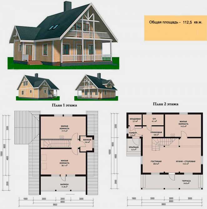
Plan of the first typical floor
Below is an image that contains a small part of the plan drawn up for a typical floor of a brick residential building. On this plan, the dimensions and dimension lines are indicated, as well as the coordination axes.
The binding of the ventilation ducts, which follow from the basement and are therefore marked with the letter P, is given along the axis B, in the longitudinal wall. For construction ventilation ducts in transverse walls, wall sweeps with channels are used, which belong to the category of special drawings. The plans indicate in which direction all the doors depicted on them should open. On the plan below, in accordance with accepted and current rules and regulations fire safety, it is shown that the entrance doors should open outward, and those that lead to the apartment - inward. To designate window blocks on the plan, grades OK2 and OK3 are used. Mezzanines are depicted using rectangles with diagonals made by dashed lines.
The position of the cutting planes necessary to create the corresponding cuts is shown on the plan by open lines 1 - 1 and 2 - 2.
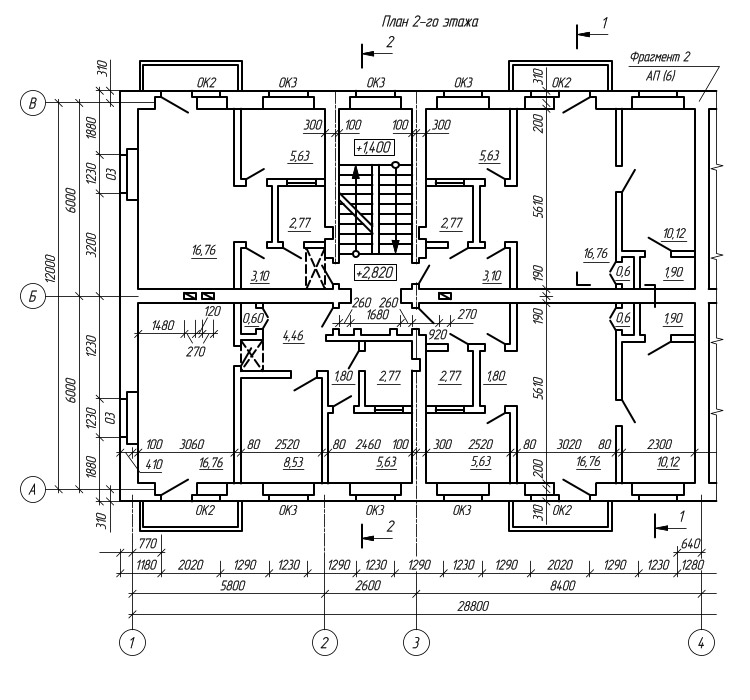
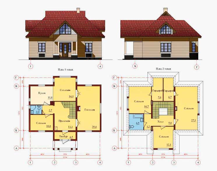
Plan of the second typical floor
According to the current rules, the dimensions of individual rooms on floor plans are not displayed. The fact is that they are supplemented by such a document as a section plan, which has a larger scale. It indicates not only all the necessary dimensions, but also partition markings (PG), door markings (D). In addition, the section plan also produces equipment designation kitchens and bathrooms.
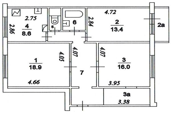
The figure below shows an image of a fragment of sections of the building in which a two-room apartment of a typical layout is located. This plan shows:
Dimensions of all rooms
Areas of all rooms (underlined numbers)
Residential and usable area of the apartment (indicated with a fraction)
Brands of door blocks (DK, D2, D3, D4)
Brands of balcony door blocks (BDU1p)
Partitions (PG6, PGS21)
Transoms (F4)
The partition located between two neighboring apartments along axis 4 is composite. It is formed by two partitions PG1, each of which has a thickness of 100 millimeters. The thickness of all other partitions is 80 millimeters. According to the current rules and regulations for the preparation of construction documentation, the working drawings included in the AU set can depict sanitary equipment and structural elements of buildings.
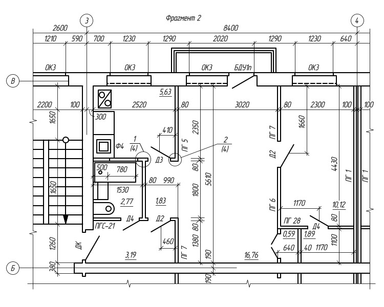
Sections of a typical floor of a residential building

Knots of wooden boxes
To depict structures such as partition panels, as well as various components and parts of wooden boxes on a larger scale, separate drawings are made. On those of them that are shown in the figure on the left, the details of nodes 1 and 2 are depicted by external elements (they are marked with circles on the plan). With the help of conditional images in the drawings of parts in sections, cement mortar, wooden elements, etc. are shown.
The list of interior finishing is included in the set of drawings of the architectural and construction part of the project. It indicates the quality and nature of the decoration of walls, floors, ceilings, partitions, as well as joinery, available in all rooms.
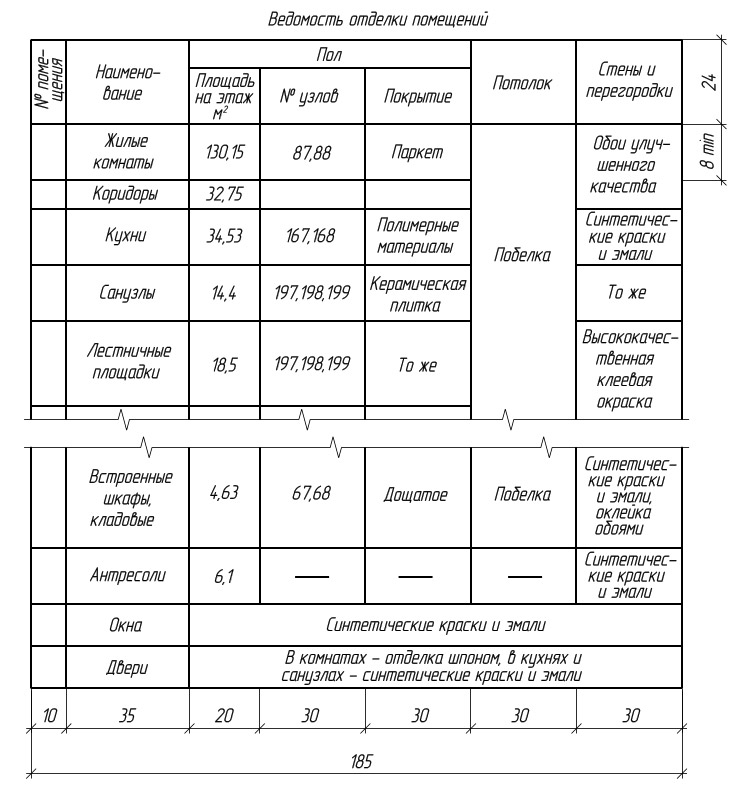
Room finishing list
When designing prefabricated buildings, all elements of which are manufactured industrially (panel, panel), floor plans are drawn schematically, and only the main dimensions are subject to application. In addition to floor plans, wiring diagrams and plans are also carried out. They show the marking and location relative to each other of all structural elements. Layout diagrams of prefabricated structures and installation plans are components of sets of drawings of the KZh brand (reinforced concrete structures).
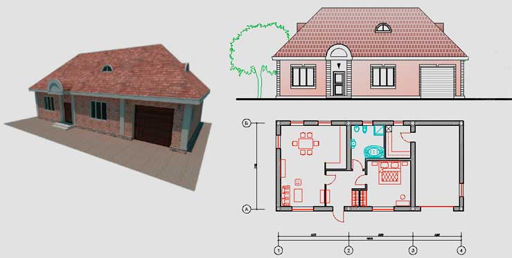
Part of the floor plan
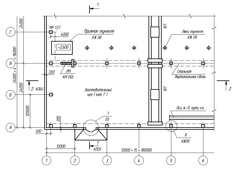
On the plan of the production building, made on a scale of 1:400, all the main elements are accompanied by both links to detail drawings (that is, remote elements) of this and other sets (KM, KZh, AR), and explanatory inscriptions. The nodes are marked with circles, the numbers of external elements are given on the shelves, a link is given to the sheets of drawings. Overhead cranes, having a carrying capacity of 10 tons, are shown by solid thin lines, the places of the cuts are determined by the lines of sections 1 - 1 and 2 - 2.
On a larger scale (1:100), "Fragment of Plan 9 at around 6,600" was made. Conditional images of the material are applied on the section of columns and partitions, in addition, quarters in window openings and elements of sanitary equipment are shown.
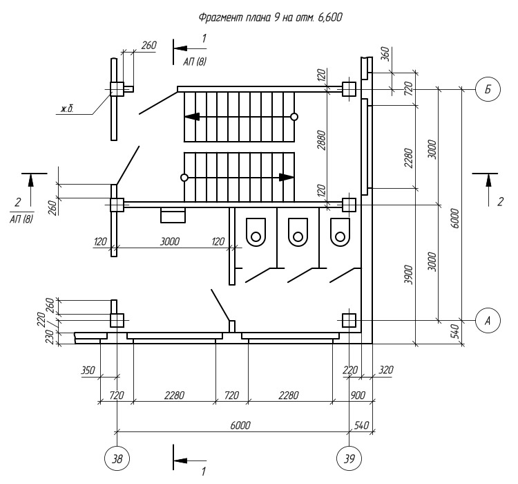
Production building plan drawing
The set of architectural and construction drawings of the AC also includes floor plans and roofs, underground rooms and structures, as well as the layout of partitions.
When purchasing a project for a future home, the homeowner must understand that there are two types of projects - typical and individual. These types of projects are separated by a number of features. But at the same time, some elements from standard projects are transferred by developers to individual ones and vice versa, borrowed design solutions from individual ones begin to be replicated in standard ones.
Individual and standard design
What is a typical project? This is a finished project, in which a detailed study of all the structural elements of the building was carried out, all the necessary calculations were carried out and working drawings were made, made in strict accordance with them. Based on the design documentation, specifications are developed, indicating the amount of materials. There are standard projects that concern only individual elements of the building, for example, the facade or individual rooms.
The project for a cottage, created individually, is based only on the realized plan of the customer. When creating an individual project, the developer is engaged in surveying the area, conducting engineering surveys and modeling the placement of a house on an allotted plot of land. It should be noted right away that the probability of meeting a copy of a building built according to such a project is extremely low.
 Plot Modeling
 Is it possible to download drawings of frame houses?
One of the motives that encourages a person to build a house outside the city is the high cost of housing in the city, while for the same money you can build a more comfortable home. One of the ways to build low-budget housing is to build a wooden or metal frame house or cottage.
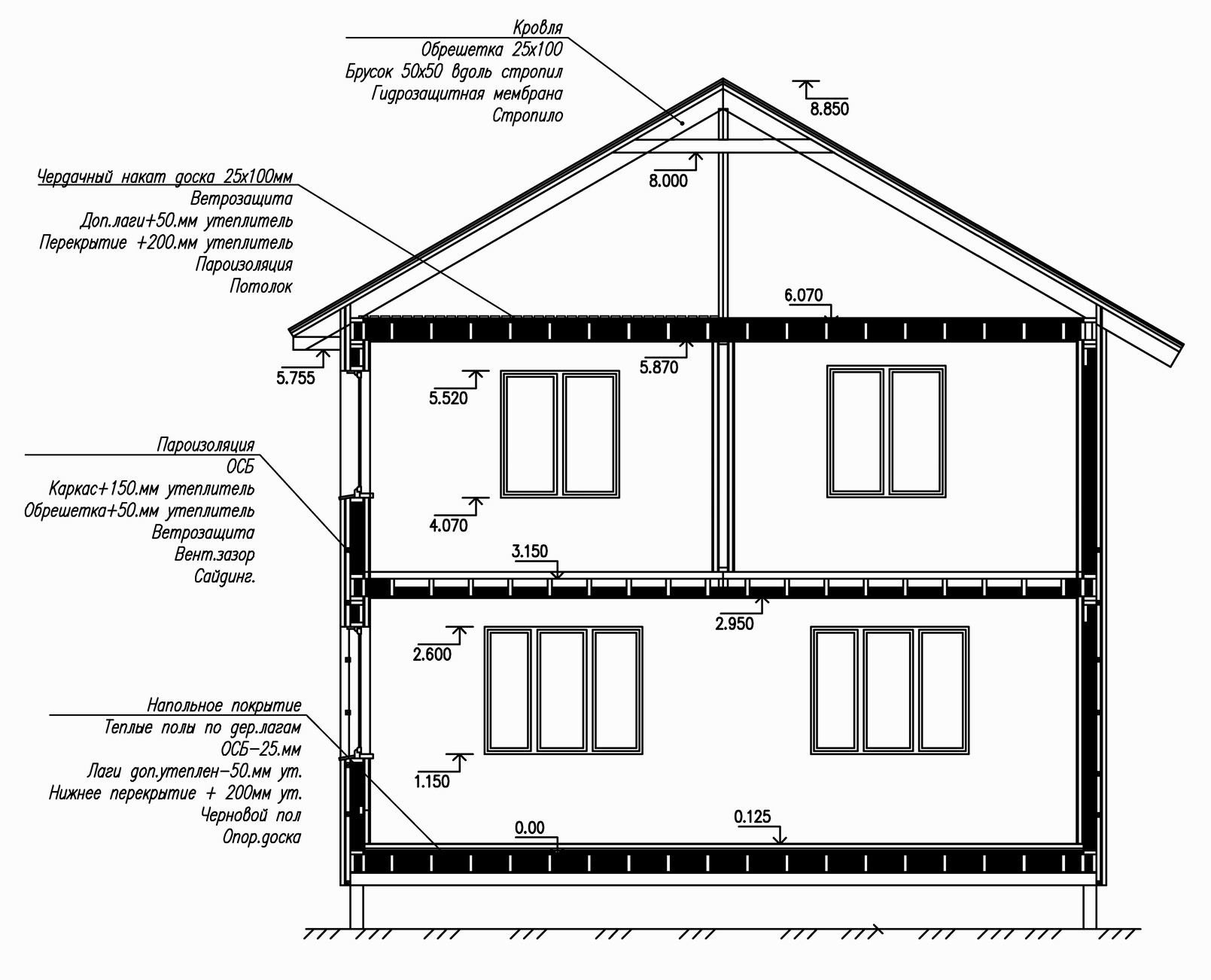 Building section
 Having made such a decision, the future homeowner begins an active search for drawings of frame houses. Thankfully, everything can be found on the Internet. A special joy for the homeowner is a set of video instructions in which, according to the authors, all the subtleties of construction are shown. But in fact, this is not quite the right approach. The fact is that construction drawings, as well as others, can be fully and correctly read only by specialists. In this case, they are civil engineers. That is, the probability of misinterpretation of the structural elements is very high, and this is a step towards the incorrect manufacture of the assembly.
In addition, you must understand that the downloaded set of drawings may be either incomplete or it is someone's unfinished development. By the way, there are no guarantees for the absence of errors in such documents.
What to do if you find good drawings?
Even if you found a free ready-made set of documentation on the Internet, it is complete, and it contains all the instructions for assembling a house, you still cannot start building. Why? Yes, because the developer of the documentation is unknown, and this is at least a reason to turn to specialists to check and adapt the set of documents found to the real conditions of the site where the construction will be carried out. It is necessary to check the possibility of manufacturing the foundation according to the drawings and its compliance with the soil.
That is, even if the downloaded documents look good, you can’t do without the involvement of third-party specialists. Indeed, formally, it is possible to start construction only after all the drawings are ready and checked by several specialists.
What should be shown in the drawings?
Drawings for a frame house are not only the embodiment of the homeowner's ideas on paper or a monitor screen. As a result, the drawings will be part of the construction work plan, which will be agreed with the organizations issuing the building permit.
The typical scale for the execution of drawing documentation ranges from 1 to 20 to 1 to 500. When using the first, everything you need will be visible in the drawings, the second scale is used when designing large buildings. When making drawings, it is necessary to use standard designations for elements of building structures, fasteners, etc. By the way, you must be prepared for the fact that during the construction process you will have to perform some additional drawings or working sketches. This is a normal phenomenon, in fact, even experienced designers find it difficult to foresee all the subtleties that arise during construction work.
There are no trifles in the documentation for a frame house, but two structures require special attention - this is the foundation and the frame. Based on the results of surveys conducted by surveyors, it is necessary to carry out the type and design of the foundation. In these documents, measures should be developed to prevent swelling of the foundation, its waterproofing, as well as the isolation of the basement or semi-basement located under the house from cold air. Accordingly, the drawings should reflect all the details of the installation of foundation structures, with an indispensable indication of the dimensions.
 Column drawings and strip foundation
 Special requirements are imposed on the documentation for the frame itself. The fact is that this is a load-bearing structure that takes on the entire load that occurs during the operation of the building. The drawings are developed only on the basis of the performed strength calculations of the frame nodes, these calculations are an integral part of the technical documentation and must be checked by specialists.
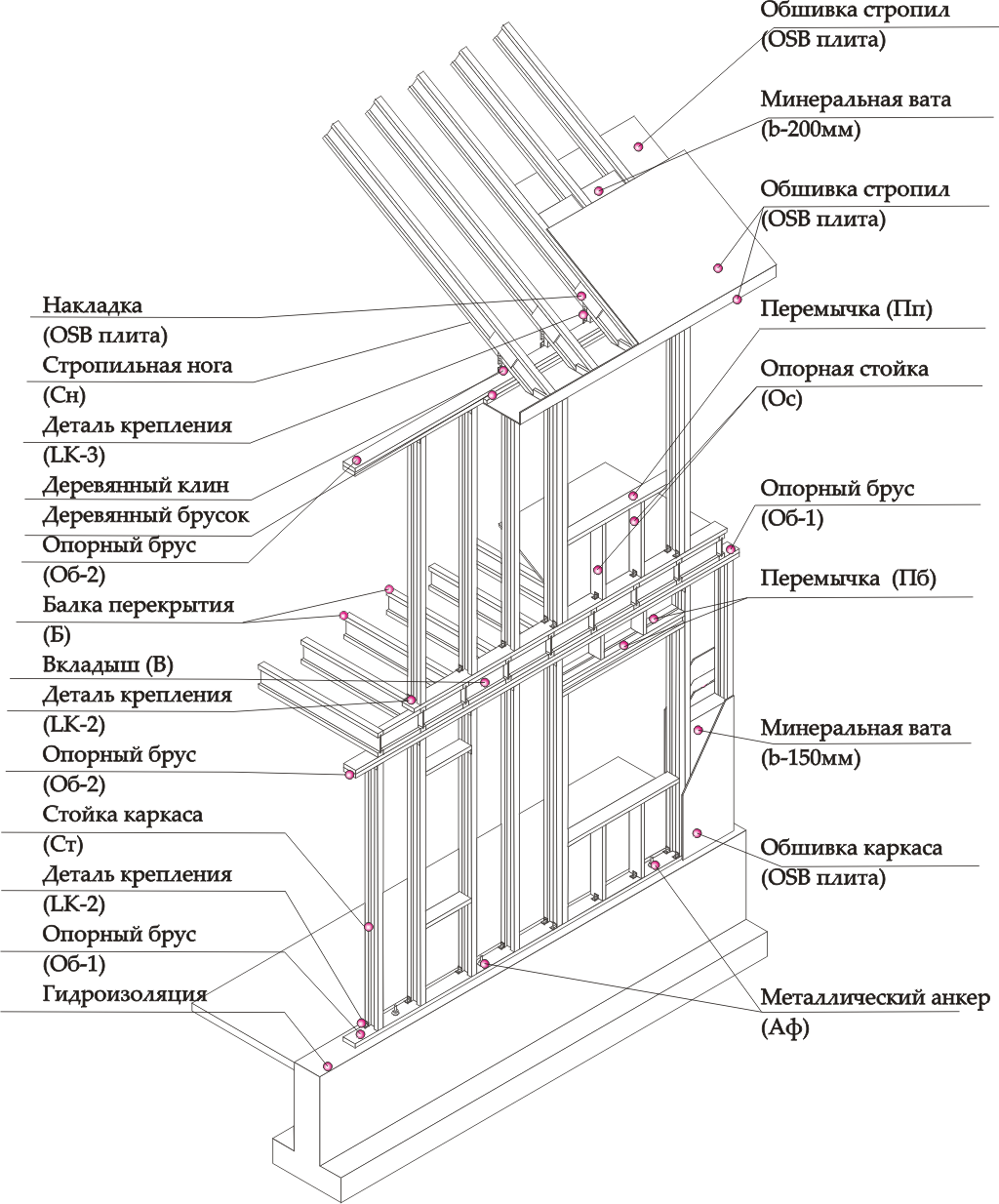 Frame diagram
 What should be included in the drawing for the walls of a frame house?
The construction of walls in a frame and frame-panel house implies that the set of drawings must necessarily contain drawings for the layout of the premises of both the entire floor and individual rooms. And it doesn’t matter if it’s a one-story house, with an attic or a garage.
They indicate the installation locations of partitions that form rooms and other premises.
For construction, it is advisable to use unified parts or assemblies, for example, door or window blocks that will be installed in walls and partitions inside the building.
Indeed, it will be easier to make several blocks with the same dimensions than the same number of window or door structures in different ways.
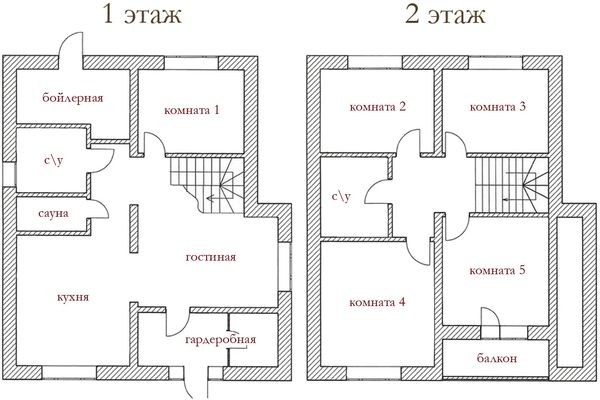 floor plan
 In the working drawings, it is necessary to indicate the dimensions of all parts used. But for clarity of the drawing, it is allowed to indicate the linear parameters of simple parts in the specification. That is, in the drawing, this part will have its serial number according to the specification, and all its parameters (dimensions, quantity) will be recorded in the specification lines. It should be noted right away that, unlike engineering drawings, builders are more condescending about the dimensions of parts and dimensional chains. When determining the limiting dimensions, as well as tolerances for them, it is advisable to be guided by GOST 21779–821 and GOST 25347–82.
The drawings should indicate the locations of all additional frame structural elements - jibs, stops. In this case, the methods of their fastening should be indicated, as in the photo.
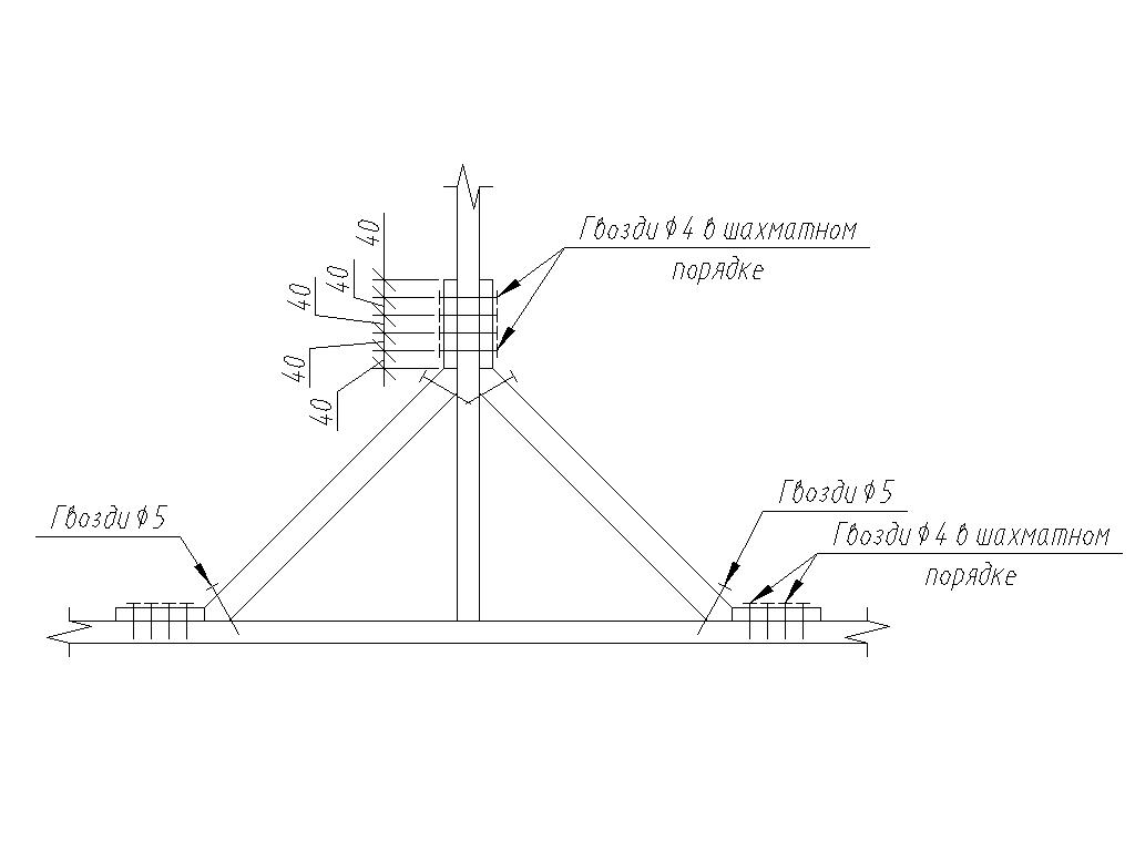 jib scheme
 In relation to the front of the building, the drawing should contain the maximum allowable information on the placement of racks, window blocks, connecting dimensions of the transverse beams.
Professional designers understand that the drawing should have exactly as many dimensions as necessary to complete the work and control what has already been done. An excessive number of applied dimensions can lead to confusion and errors.
 Floor plan
 In addition, there is a rule that engineers of all industries follow. All technical documentation should be interpreted unambiguously and there should be no discrepancies in its application.
What does a full house project include
Working project of the house
Construction can begin only after all the documentation that is necessary for construction has been completed and verified. The working draft consists of the following parts:
- Architectural and construction;
- Design;
- Schemes of installation of engineering communications;
- Schemes of installation of low-current wiring;
- Layouts of electrical equipment and power wiring.
In addition to the listed technical documents, the detailed design also includes an estimate for the construction work. All developed documents must comply with the requirements of SNiP and GOST.
All construction work performed by professionals or with their own hands must be carried out in strict accordance with the approved project of the house.
The main sections of the working draft
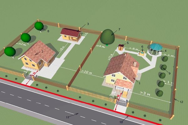
The list of documentation is given above, but it should be understood that not all of them are required. The main parts are considered architectural and construction and design. The architectural part determines the appearance of the building, linking it to the terrain, and also shows how the land around the new house will be equipped. The design part contains detailed drawings of all structural elements of the building.
 Site master plan
 When developing a building project, these parts can account for up to 70% of the cost of a complete set.
To control the quality of work, it makes sense to involve engineers for supervision.
As a rule, these are highly qualified specialists who can also revise all parts of the project documentation, coordinate it in all instances and, if necessary, point out to the designers about errors and inaccuracies made during the development process. The main part of the project can also include the part in which attention is paid to the interior design of the premises.
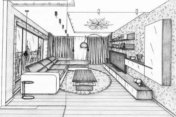 interior sketch
 Exactly as planned
The quality of the future home depends entirely on the correctness of the work, that is, all work must be carried out in strict accordance with the drawings and technological schemes. All the arguments of the builders, that it will go like this, must be immediately swept aside. Once again, all documentation is carried out in accordance with the norms and rules of construction, and their violation can lead to unpleasant consequences. This applies to all types of work and the procedure for manufacturing the foundation, including its insulation.
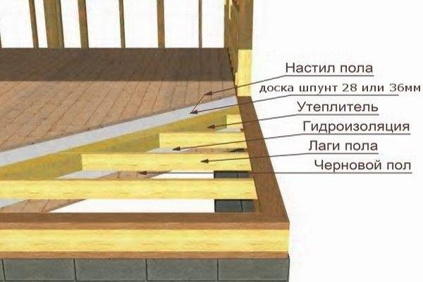 floor plan in frame house
 In fact, independent design of a house can be carried out only with applied knowledge in construction. For those who do not have such knowledge, it is easier to buy a ready-made project 4x6, 6x6, 6x8, 6x9, 8x8 in the company that will be engaged in the construction and commissioning of the turnkey facility. The presence of a single contractor immediately removes many questions.
Video
Watch a video about a set of drawings and documents required for the construction of a frame house.