To date, the most popular guide mechanisms for drawers are telescopic (ball) and roller. Not only the service life of the product, but also the ease of use of furniture will depend on the correctness of their installation. Therefore, further it will be considered how to install the guides for drawers with your own hands.
Installing ball guides
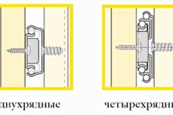
According to the design features, telescopic guides for boxes of different companies may differ slightly, but the base for all has the same appearance: it consists of balls that move along stamped grooves. Such products can be 2- and 4-row. The second type is considered more durable, it can withstand a fairly large load (about 30-40 kg).
Telescopic slides for drawers have such advantages as:
- ease of installation;
- easy and silent movement;
- the ability to withstand heavy weight;
- long service life.
Among the shortcomings of such structures, it is worth highlighting the rather high price and the need for precise assembly.
For installation work, you need to prepare the following tools and materials:
- drill with a drill;
- screwdriver or screwdriver;
- simple pencil;
- ruler;
- guides;
- fasteners.
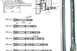
For correct installation it is necessary to calculate as accurately as possible all the dimensions of the parts and their attachment points. There should be small gaps about 12 mm wide on the sides of the assembled box and on the sides of the furniture. This should be taken into account when calculating the dimensions of the furniture. The depth of the drawer and the length of the rails must be the same. The standard dimensions of the telescopic mechanism can be from 25 to 80 cm with a length difference of 5 cm between the following models.
The principle of mounting ball guides is quite simple. First, the telescopes are disassembled into 2 parts, one of which is installed on the inner side of the furniture, and the second on the side of the box. In this case, the main and most difficult task is to accurately determine the attachment points of the product. To do this, a line is marked horizontally and strictly in the center on the side of the box, along which one half of the guide mechanism is screwed with screws.
After that, a similar horizontal line should be marked on the inner wall of the cabinet. To do this, you can use the drawing of a furniture product. After that, the second half of the telescope is attached along the marked line.
If everything is done correctly, then you can try to insert the removable parts of the mount located on the box into the grooves of the guides and connect them. In this case, both parts of the product should smoothly enter into each other, and the drawer should be easy to move along them. Otherwise, everything will need to be done all over again.
Back to index
Roller elements
This mechanism is the simplest in terms of device and installation, having a low price. It is able to withstand a load of no more than 25 kg, so it is unlikely that you can store a lot of things in such a box. If it is incorrect to calculate and install roller guides, then they will quickly fail. Therefore, the process of work should be approached with all responsibility.
First of all, on the basis of the furniture drawing, an accurate marking of the places where the mechanism is attached is made. After that, a non-through hole for the screw is drilled (its depth should be about 13 mm). Next, 2 more of the same holes are created, the location of which is determined by the drawing.
At the next stage, a guide element is placed on the box in such a way that the end of the part, on which there is no roller, abuts against the front wall of the box. The wheel should be placed at the back of the drawer. With the help of screws or screws supplied with the product, the roller guide is fixed in place. In the same way, fastening is made on the other side of the box.
Next, they proceed to the installation of guides on the walls of the furniture itself. Here they are placed perpendicular to the facade of the furniture product. In this case, the ball should be in front, not behind. Usually all guides have round and elongated screw holes.
For many, it is not possible to do all the installation work the first time. In this case, you will need to disassemble the product and re-mark it to achieve the desired result.
Hello dear reader! More and more customers are ordering furniture with concealed rails. And I understand them perfectly, guides are superior in quality to ball ones. In addition, the interior space of the cabinet is used to the maximum.
The drawer looks spectacular because of the hidden rails. Ride is comparable to expensive brands. Excellent working closer, allows you to enjoy the silence. Easy installation and dismantling of the system.
Features of the calculation of flush-mounted guides
To calculate the front slats of the drawer, subtract 41 mm from the internal width of the cabinet. For the side, subtract 10 from the length of the guides. Cabinet width 400. Internal solution 368 - 41 \u003d 327 the length of the front bar. The guide is 450, which means the length of the side is 440.
The height of the drawer slats has its own peculiarity. The side ones are calculated 16 mm more than the front ones. To hide the guides and drive the bottom of the drawer into the groove. The distance to the groove on the side is equal to the height of the front slats of the drawer.
Within walking distance from you, located according to the calculation of cabinet furniture.
Marking flush-mounted guides
The markings on the sidewalls are made based on the height of the sheflots. The fastening line should be drawn at least 45 mm higher from the bottom of the pedestal or the edge of the lower headboard. Do not forget that the width of the sidewall should be 10 mm more than the length of the guide.
The instructions indicate that the guide should be fixed in the fourth hole to a depth of 37 mm. Having secured in this way, the sheflot did not press tightly against the ends of the sidewall. Shifted by 39 mm and the gap disappeared. I used Boyard's flush-mounted guides.
Installation of concealed rails
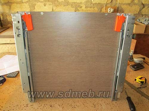
To install the drawer, it is necessary to make two holes with a diameter of 6 mm, in the rear front plate, on the outside of the drawer. At a height of 11 mm from the bottom of the drawer and 23 mm from the side rail. For fixation from the back.
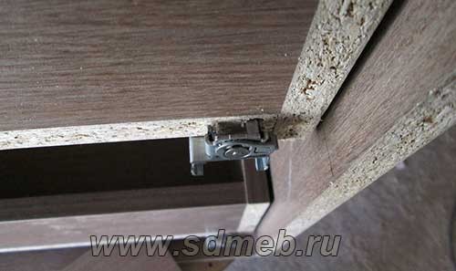
For fastening from the front side, to the bottom of the box, flush with the edge, we fasten the clamps. They snap the flush-mounted rails onto the drawer. To remove the box, just press the blue flags and lift the box up.
Outcome
Now you know what I know. You are able to install flush-mounted rails without unnecessary movements. The system is very simple and requires no mental effort. Follow the instructions and enjoy the smooth ride!
If you need detailing cabinet or built-in furniture,. We will certainly discuss the terms of cooperation and come to a consensus. For a moderate percentage for my work, I will prepare a detailed project for you on time.
What would you like to add to this article?
Tell me about your experience in the comments.
I would love to hear your stories!
With good thoughts about you, furniture expert
Rekun Dmitry.
In this article, I propose to consider the calculation of drawers for them.
If you have read an article about this sliding system, then you probably already know that drawers for it are designed and assembled in a completely different way than for other guides (the same "").
The height of their side (dya2) and frontal (dya1) parts is different, and the bottom, which is slightly offset relative to the bottom, is made of chipboard.
As a result of this, protrusions are obtained on the sides of such a box, between which the guides themselves (in the installed version) should be located.
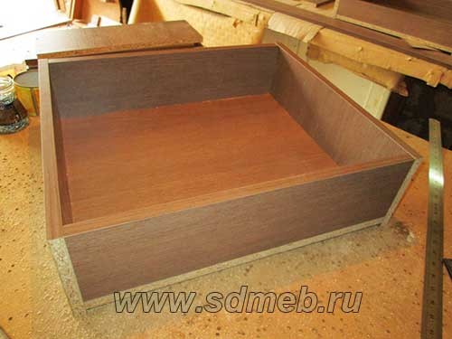
 The size of such a protrusion should be within 13 millimeters.
So let's take a look at the calculation specific example(so it will be more clear).
All values proposed in the following will be measured in millimeters.
First, we calculate the dimensions of the parts in width (depth).
In order to find out the width of the front parts (dya1), you need to subtract 42 from the size of the box body strip.
In this case, the width of the box body strip (width 550) will be equal to:
Now, subtract 42 from this value, and get the width (dya1):
Since the depth of the box in which we are designing the box is 460, then the guide for it will fit 450.
To find out the size (dia2), you need to subtract 10 from the size of the guide (450):
Now you need to decide on the dimensions of the details of the box in height.
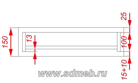
When assembled, protrude down 15 under the drawer (see picture below).
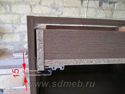 This must be taken into account when choosing a height.
So, if we take the height of the box (and, to be more precise, it will be the height of the parts (dya2)) equal to 100, and suppose that there should still be a gap of 10 at the bottom of the guides, then let's estimate how much free space will remain for the overlap body strips from above:
150-100-15-10=25, where 150 is the height of the facade, 100 is the height of the drawer, 15 is the protrusion of the system from below, 10 is the free gap.
 Excellent.
The body strips overlap and there is still a normal gap.
Well, the height (dya1) is determined taking into account the fact that the bottom of the box is made of chipboard, and it must be shifted relative to the details (dya2) by 13:
Well, finally, we calculate the dimensions of the bottom itself.
The width of the bottom will be equal to the width of the part (dya1), that is, 476
The depth will be equal to the part size (dya2), i.e. 440.
So, now we can write down the details:
- dia1 - 71x476 (2pcs)
- dia2 - 100x440 (2pcs)
- bottom - 440x476
But that's not all.
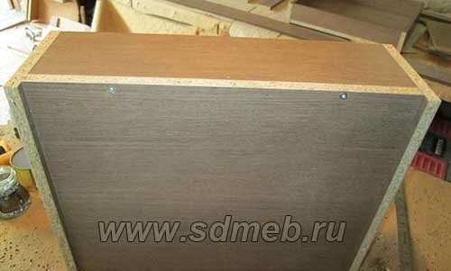
From the rear edge of this box, you need to make two holes with a diameter of 6 mm, according to the dimensions indicated in the figures below.
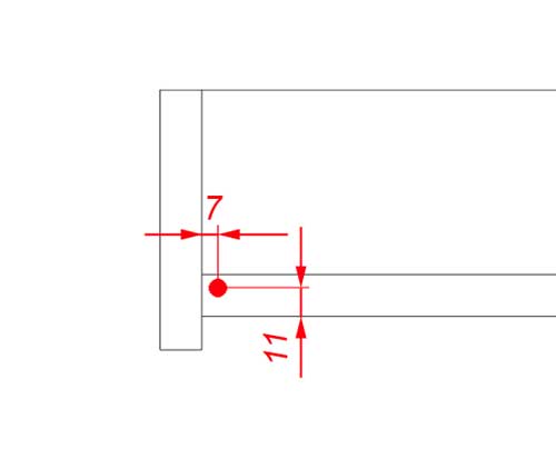
 Through these holes, retractable system fixes the box.
We will talk about how to do it for installation in a separate article.
And that's probably all, until we meet again!
The mounting dimensions of the rails on the side of the pedestal will be given taking into account the possible interchangeability of the drawers. The calculation and example is given on the basis of a three-drawer kitchen cabinet-section (Fig. 2.). At the end, a fully parametric model of such a pedestal with all fittings will be given, for a more detailed acquaintance. PRO100 model in "*.sto" format.
All calculations are made on chipboard 16 mm thick.
Box length.
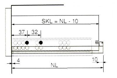 Fig.3
Fig.3
where, NL is the nominal length of the guide. SKL - box length. SKL = NL - 10 mm.
Box width.
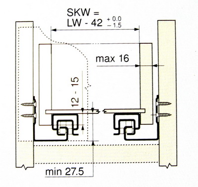 Fig.4
Fig.4
where, LW is the internal size of the pedestal (between the sidewalls). SKW - the length of the front or rear part of the box (provided that this part is placed between its sides).
Box height.
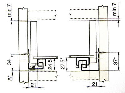 Fig.5
Fig.5
Scheme for calculating the height of the box.
Practical part. Calculation and installation.
In practical application, let's move away a little from the catalog schemes, and make a scheme for ourselves. See fig.6. black numbers- dimensions of the body, drawer sides, fronts and gaps. red- dimensions for fastening guides. blue- the size of the front and rear panels of the drawers. green- gaps of the box body between other parts.
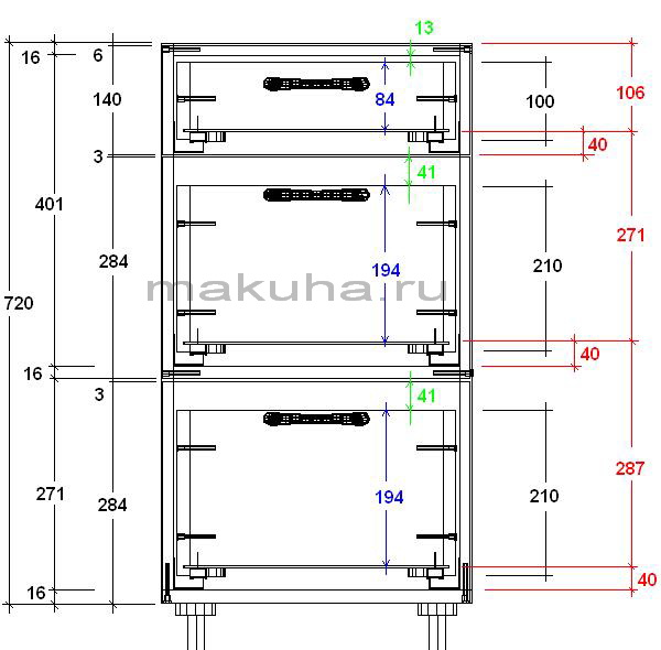 Fig.6
Fig.6
With this scheme, the lower and middle drawers turned out to be interchangeable.
Diagram of a box for tandems.
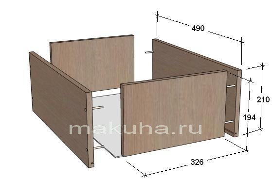 Fig.7
Fig.7
The Bloom catalog suggests making drawers with a groove for fiberboard in all four parts, and then making cutouts in the front and back parts for the clamps. What for? It is quite enough to make only grooves in the sides of the box, and the front and rear walls decrease in height accordingly.
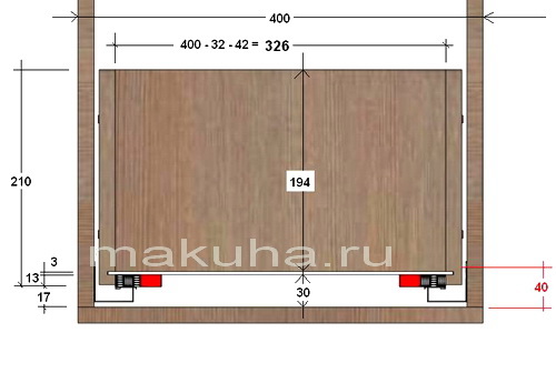 Fig.8
Fig.8
We take the length of the sidewall of the box, as in the catalog. Those. 500 mm - 10 mm = 490 mm.
Then, drawer detail dimensions:
- Sidewalls of big boxes - 490 x 210 mm.
- Front and back details of big boxes - 326 x 194 mm.
- Sidewalls of the top box - 490 x 100 mm.
- Front and rear details of the top drawer - 326 x 84 mm.
Cabinet depth.
When mounted to the side of the pedestal, the guides are fixed by 4 mm. from the front edge of the sidewall. From here, minimum the depth dimension (width of the cabinet side part) should be = Length of the guide + 4 mm. For convenience, the depth of the cabinet should be considered as follows: Length of the guide + 10 mm. In our version, with a guide length of 500 mm. the depth of the pedestal will be = 510 mm.
Assembly.
1. Fastening guides.
2. Assembly of boxes.
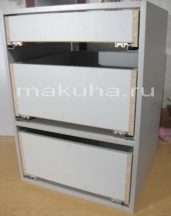 Curbstone with boxes on Tandems assembled.
Outcome. General formulas.
- Cabinet side = Tandem rail length + 10 mm.
- Drawer side = Tandem rail length - 10 mm.
- = pedestal width - 32 mm. (thickness of cabinet sides) - 42 mm. (catalogue size).
- Drawer side height (for facades from 200 mm high.) = Front height - 40-41 mm. (gap on top) - 17 mm. (gap from the lower edge of the facade or from the bottom, connections).
- Drawer front and rear panel height = drawer side height - 16 mm.
- Drawer side height (for fronts less than 200 mm high.) = Front height - 23 mm. (gap from the top of the facade) - 17 mm. (gap from the bottom of the facade).
- The bottom of the box is made of fiberboard. Width = Drawer front and rear panel length + How to drill assembly holes.
Can be copied with reference to the source and an active indexed hyperlink to the site