CENTRAL BUREAU OF LABOR STANDARDS AT THE SCIENTIFIC RESEARCH INSTITUTE OF LABOR
STATE COMMITTEE OF THE USSR COUNCIL OF MINISTERS ON LABOR AND WAGES
Issue III
NORMALIZED FASTENERS
Moscow - 1975
CENTRAL BUREAU OF LABOR STANDARDS UNDER THE LABOR RESEARCH INSTITUTE OF THE STATE COMMITTEE OF THE USSR COUNCIL OF MINISTERS ON LABOR AND WAGES
GENERAL MACHINE-BUILDING TYPICAL TIME RATES for machining machine parts
Issue 111 NORMALIZED FASTENERS
General machine-building standard norms of time for machining machine parts. Issue III. Normalized Fasteners
Standard standards are intended for raters, technologists and other engineering and technical workers involved in the development of technically sound standards for the processing of normalized fasteners in non-specialized metalworking shops (sites) of enterprises.
Standard time norms are approved and recommended for use at enterprises by the section of the Expert and Methodological Council of the Central Bank of Science and Technology and approved by the State Committee of the USSR Council of Ministers on Labor and Wages (Decree No. 208 of August 15, 1972) and agreed with the All-Union Central Council of Trade Unions.
The collection was developed by the Central Bureau of Labor Standards with the participation of enterprises and regulatory organizations of various machine-building ministries.
These model standards are a revised and supplemented edition of previously issued standards and are introduced to replace the collection of the 1964-1965 edition.
The collection corresponds to the 1975 edition.
Please send all comments and suggestions on this collection to the address: 103112, Moscow, KL2, pl. Kuibysheva, 1, TsBNT.
© Research Institute of Labor of the State Committee of the Council of Ministers of the USSR on Labor and Wages (Research Institute of Labor), 1975
A COMMON PART
These standard time standards are recommended for standardizing machine work in the manufacture of normalized fastening ds-hoists of machines in non-specialized workshops of machine-building enterprises performed on lathes, turret-turning, drilling, grinding and other machines for small-scale and mass production conditions and on single-spindle automatic lathes - for serial "and large-scale production.
When developing this collection, the accepted nomenclature of parts was brought into line with the requirements of newly issued and revised GOSTs.
With the revision of the standard norms of the 1964 edition, the collection was significantly expanded. Additionally, the time standards for processing fasteners on single-spindle automatic lathes are given. The collection is supplemented with maps for knurling and calibrating threads, grinding smooth surfaces, processing pins, etc.
The following materials are the basis for the development of standard time standards:
1. General machine-building standards for cutting modes for technical regulation of work on metal-cutting machines. M., "Engineering", 1967.
2. General engineering standards for auxiliary time, for servicing the workplace and preparatory and final time when working on metal-cutting machines (small-scale and single production). M., Research Institute of Labor, 1968.
3. General engineering standards for auxiliary time, for servicing the workplace and preparatory and final for the technical regulation of machine work (serial production). M., Research Institute of Labor, 1968.
4. General machine-building standards for time and cutting conditions for automatic turning work (mass, large-scale and serial production). M., "Engineering", 1971.
When developing standard time standards, along with the above general machine building standards, the following were used:
1. GOSTs for fasteners (see the list of parts on page 20).
2. Technological processes, cutting conditions used in enterprises and chronometric observations in production conditions for the time spent on machine tool processing of fasteners.
3. Industry and local fastener manufacturing times.
4. Passport data for equipment.
b. Analysis results labor processes, the study of rational labor methods and the organization of the workplace.
The time limits in the collection are given in minutes. Limits of numerical indicators (length, diameter, etc.) for which "up to" is indicated should be understood inclusive.
The collection of standard time norms consists of the following sections:
A common part;
Characteristics of the equipment used and technology of work;
Labour Organization;
Regulatory part;
Applications.
Typical norms of time for machining fasteners are a complete type of enlargement, when for each operation the norms of piece and preparatory-final time are given.
For the convenience of using the collection in the maps of standard norms, time is given for the complete processing of parts, and individual processing options are also highlighted.
Typical operating times include:
a) main (technological) time;
B) auxiliary time for installation and removal of the part;
c) auxiliary time associated with the transition;
d) - time for maintenance of the workplace, rest and personal care (within 5 to 10% of the operational time, depending on the type of work).
Partial piece time includes the same components, with the exception of auxiliary time for installation and removal.
Preparatory final time in the collection is given in relation to the types of machine tools (chart 62). This time, set for a batch of machined parts, provides for the following scope of work:
1. Obtaining an order and technical documentation.
2. Familiarization with the work, drawings and receiving instructions from the master.
3. Obtaining tools and fixtures, preparing the workplace, setting up equipment, tools and fixtures.
4. Removal of tools and fixtures at the end of the processing of a batch of parts, their delivery.
5. Partial readjustment of equipment in the course of work.
Typical time standards are designed for organizational and technical conditions corresponding to the accepted type of production. The size of the batch of parts taken as a unit, and correction factors for changed working conditions are given after the piece time cards by type of machine.
For single-spindle automatic lathes, the batch of parts accepted is more than 500 pcs.
If the machine systematically performs the same type of operations on
4
processing structurally similar parts, piece time, given in these standard norms, must be corrected by the coefficient /("0.70.
Typical time limits are calculated to supplement the work with one-station maintenance. In the case of multi-machine maintenance, standard norms should be applied with coefficients:
The level of labor productivity adopted in the standard norms takes into account the experience of the work of machine shops of machine-building enterprises.
In cases where the time norms in force at the enterprise are less than standard norms, these more progressive time norms should not be increased.
With the entry into force of these model standards, the collection of the edition of 1964 or 1966 is canceled.
When establishing time norms at enterprises based on the standard time norms of this collection, the billing of work should be carried out according to the Unified Tariff and Qualification Reference Book of Works and Professions of Workers, Issue 2, approved by the Decree of the State Committee of the Council of Ministers of the USSR on Labor and Wages and the All-Union Central Council of Trade Unions No. 22 of 21 January 1969, subject to subsequent additions and changes to it.
The discrepancy between the qualifications of the worker and the established category of work cannot serve as a basis for any changes in the norms of time in the collection.
Characteristics of the equipment used and technology
work
The technical characteristics of representative machines, passport data, which were taken into account when choosing cutting conditions, are presented in the table below.
The technical and technological characteristics of the above models of machine tools is that they have a complete set of feeds, speeds and sufficient power.
|
Machine type |
Options |
Power ■ k*t |
Main motion speed limits in rpm |
Falling limits in mm/rev |
|||
|
Milling |
5 front surface |
Longitudinal transverse vertical |
|||||
|
longitudinal transverse vertical |
|||||||
|
Smolilny |
Maximum drilling diameter | ||||||
|
Krugloshlnfs-eal |
Maximum grinding diameter Maximum grinding length |
workpiece 30-235 |
Speeds moved* table in m/min 200 - 6000 Cross feed of the grinding headstock in one stroke 0.01-0.02; 0.03-0.01 |
||||
Continuation
|
Stayak type" |
Options |
The speed limits of the main movement in about! mime |
Feed limits in mm/rev |
||||
|
Cradle-free-roller-hip machine |
Sanding diameter |
largest least | |||||
|
work piece length |
|||||||
|
Thread-cutting semi-automatic machine with a rotating head | (Bolt-cutting) | |||||||
|
Threading machine with round rollers A |
The largest diameter of the thread to be cut | ||||||
|
Single spindle lathe ga tomato |
The largest processing diameter |
1150 - 7800 800-7670 550-3200 | |||||
Typical time standards are designed for the following technologies under conditions:
L. The piece time in the cards is set for the processing of parts made of structural carbon steels a * "60-76 kg / mm 2. When processing parts with a tool made of high-speed steel, coefficients are provided depending on the grade of the material being processed. When machining parts using carbide tools, correction factors are given depending on the strength of the material being machined.
B. A workpiece used for calculating piece time when processing parts on lathes and turret lathes, for parts with a diameter of up to 20 mm - a bar 1000 mm long, for parts with a diameter of more than 20 mm - a separate workpiece from rolled products, stamping or forging. When processing parts on single-spindle automatic lathes, a bar 3000 mm long is taken as a workpiece.
3. Installation of parts is carried out in universal fixtures.
4. Technological modes of work on lathes and turret lathes for cutters are designed for the use of carbide tools. All other types of machining (except grinding and thread rolling) are performed with a cutting tool made of high-speed steel. For automatic processing, the norms are also calculated with the condition of using a tool made of high-speed steel.
6. Typical standards for the processing of bolts, screws and nuts on lathes and turrets are calculated for threading the 3rd accuracy class. In the case of threading of the 2nd class, a correction factor /("U,2.
<6. В случае изготовления детали ко отдельной заготовки, штамповки или поковки время на отрезку не учитывалось.
7. The time limits for grinding are calculated based on the condition of removing the allowance of 0/1 mm per side.
8. In the norms of piece time, the alignment of bolts and screws is taken into account for processing them with lodging by the center of the tailstock at a ratio of the length of the part to the diameter of 8-<10 и рассверливание отверстий в гайках, начиная с диаметра резьбы 30 мм.
9. When cutting threads on lathes and turrets, the use of taps and dies for diameters up to 20 mm and cutters for diameters over 20 mm is taken into account in the norms of piece time.
Labour Organization
With a rational organization of labor, the workplace must be equipped in accordance with the requirements of the production process and the conditions for performing work in compliance with the rules of sanitation and hygiene and safety.
The location of equipment at the workplace, inventory, industrial furniture, containers, racks for blanks and finished products is planned in such a way that there are no cramped working conditions, extra costs, time for walking and searching.
The equipment of the workplace must be sufficient and correct. The required illumination is determined by the nature of the work being done and the current sanitary standards.
In natural and artificial lighting, it is recommended to place workplaces in such a way that the light falls on the left or in front. In the presence of local lighting, the light should not blind the eyes, the shadow should not fall on the workpiece.
The external design of workplaces and industrial premises must comply with the requirements of technical aesthetics.
The number of tools and fixtures at the workplace should be ". the minimum necessary to ensure uninterrupted operation during the shift with the least time spent on obtaining and replacing them.
Tools and fixtures should be located at the workplace in a certain order, convenient for use.
Cleaning of chips and waste at the workplace is carried out by production and workers, from workplaces - by cleaners of workshop production facilities.
The number of parts to be processed, workpieces at the workplace is determined by the production organization system and must ensure continuous operation during the shift.
At the workplace, there is an instructional and operational map for choosing erysipelas-in-cutting according to the type developed by the Nevsky machine-cTpoH \ v .. oHWM plant named after. V. I. Lenin or PKTImash (see Appendix 2).
Below are some schemes for organizing jobs for machine operators, taking into account the requirements for organizing workers in the county.
Scheme of the organization of the workplace of a turner
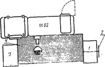
/ - instrumental bedside table; 2 - tablet for hanging drawings; 3 - reception table; 4 - lattice for legs
The turner's workplace is equipped with a tool cabinet for two-shift work (see Fig. 7), at each distance of which a permanent set of tools and equipment for caring for equipment is stored, as well as a receiving table (see Fig. 8).
1 - instrumental bedside table; 2 - tablet for hanging drawings of workpieces; 3 - lattice for legs; 4 - reception table; 5 - rack for horizontal storage of bars
The workplace of the revolver is equipped with a tool cabinet installed to the right of it for two-shift work (<см. рис. 7), приемным столиком (ом. рис. 8), установленным слева.
A container for finished parts is installed on the upper plate of the receiving table; the lower shelf can store accessories for the machine. If (the turret machine is designed for bar and cartridge processing, then the racked container with blanks is placed in an empty place behind the tool cabinet. For turret machines intended only for chuck processing, two containers are installed on the receiving table (for blanks and for finished parts); and the stock of blanks in the stela and the fattening container is located to the right of the worker behind the tool cabinet.
The driller's workplace is equipped with a tool cabinet for two-shift work (see Fig. 7), in each compartment of which there is a permanent set of tools, and a receiving table (see Fig. 8), placed on the left. On the bottom shelf of the receiving table are stored small devices.
Scheme of organizing the workplace of a revolver

Scheme of the organization of the workplace of a driller working on a vertical drilling machine
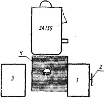
1 - tool cabinet. share; 2-tablet for hanging drawings of workpieces; 3 - reception table; 4 foot grate
The set of tools necessary for direct work is placed on the top shelf of the nightstand.
Scheme of the organization of the workplace of the milling machine

/ - instrumental bedside table; 2-. plaque for hanging drawings of workpieces; 3 - reception table; 4 - lattice for legs; 5-rack for fixtures and accessories; 6 - rack for mandrels and boring bars
The workplace of the miller is equipped with a tool cabinet for two-shift work (om. Fig. 7), in each compartment of which a permanent set of tools was stored.
The bedside table is installed to the right of the worker, and a receiving table is placed to the left (see Fig. 8) for two containers. Attachments and accessories for the machine are placed on a rack with a sliding platform (see Fig. 9) installed behind the machine.
With an increased stock of parts intended for processing, they are placed in a rack container or on pallets on the back of the machine.
Scheme of the organization of the workplace of the grinder

1 - reception table with tool boxes; 2 - mobile reception table; 3-tablet for hanging drawings of workpieces; 4-balancing device for a group of machines
When working with an abrasive tool, the rules of safety and industrial hygiene do not allow long-term storage of it at the workplace, therefore, only machine accessories and a universal measuring tool are included in the permanent set of the grinder's tool.
Based on this, the workplace of the grinder is equipped not with a tool cabinet, but with a receiving table with tool boxes (the number of boxes is determined in each specific case), in which a set of tools is stored (see Fig. 10).
For convenience, the grinder's workplace is equipped with a movable receiving table (see Fig. Ill), on which the tool necessary for work is placed.
Scheme of the layout of the automatic processing area
/ - single-spindle lathe machine 1A-Sh8; 2 - lathe single-spindle machine 1A124; 3 - reception table; 4 - "receiving table with tool boxes; 5-rack for horizontal storage of bars; 6 - adjuster's cabinet
Typical for automatic sections is multi-machine maintenance and adjustment of equipment by an adjuster. Therefore, in the automatic puff sections, not a separate workplace is equipped, but the site as a whole. The described area is equipped with a fitter's cabinet (see Fig. 12), receiving tables (see Fig. 8, 10) and racks for storing bars (see Fig. 10).
Receiving tables are designed to place on them containers with finished parts and the measuring tool that is directly necessary in the work (gauges, templates, etc.). The container with finished parts is transferred to the workplace of the Quality Control Department using a yura-beam. The number of bars a worker needs for a shift is fed to the machine before the start of the shift. The bars are placed on racks made up of two or three sections connected to each other. The location of the racks is determined by the design of the equipment and the convenience of refilling the bars into the machine.
One of the receiving tables at a group of machines serviced by one worker has tool boxes in which the worker stores the necessary tools.
Organizational equipment of workplaces
The bedside table is designed to store the necessary tools at the workplaces of machine operators, documentation and equipment care products.
Each compartment of the nightstand is closed with a door and is assigned to one worker. The compartments have tool boxes and shelves for storing documentation, non-bold accessories and fixtures, oilers, cleaning materials, etc.
The top shelf of the nightstand can be covered with plastic. A removable plate for attaching drawings and a technological process, made of decorative wood-laminated plastic, is fixed in brackets.
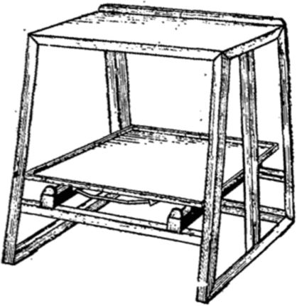
Reception table
On the top shelf of the table there is a container with processed parts or the parts themselves. If necessary, fixtures and accessories can be stored on the lower shelf.
At individual workplaces, the table can be used to place on it the tool used in the work.
Accessory rack with pull-out platform
The platform moves on rollers and has a stroke limiter. The details of the rack are made of bent profile and steel sheet. The top shelf and platform are made of wood impregnated with phenol-formaldehyde resin.
Reception table with tool boxes
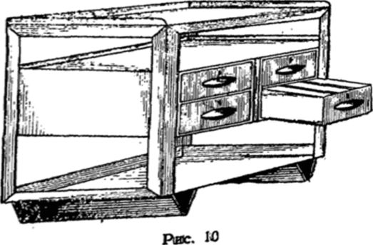
DESK DRAWER Used for storing tools, and the top shelf for placing containers with parts or for laying out tools necessary for the job.
The design provides for the possibility of installing two or four * gyreh tool boxes. When installing four drawers, two of them are placed on a hanger with rails, attached balls and racks.
The boxes move easily on rollers and have a travel limiter. they can be installed adjustable partitions, forming cells and the desired size. Between the top shelf and drawers there is space for technical documentation. On the back side of the table there are brackets for mounting on the documentation tablet. Olika parts are made of bent profile and steel sheet.
Mobile reception table
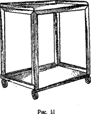
The table is used on those working bridges where, due to the working conditions, stationary office equipment (tool cabinets or reception tables) cannot be installed close enough and conveniently near the machine.
On the upper and lower shelves of the table, the worker lays out the tool he needs in his work and sets the table in the most convenient place for himself. The details of the table are made of bent profile and steel sheet. If necessary, the table can be equipped with a handle for ease of movement.
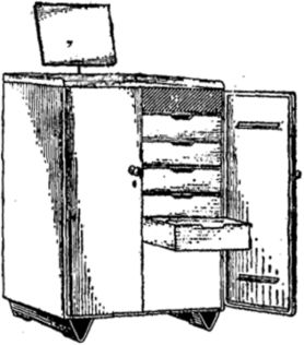
Wardrobe

Rice. No.
The cabinet consists of individual elements (base, boom and rear stacks, doors, storage drawers and shelves). Shelves can be re-stashp> but height. Adjustable partitions can be installed in drawers and on shelves, forming cells of the desired size. To accommodate a long tool in the cavity of the doors, one. distant holders.
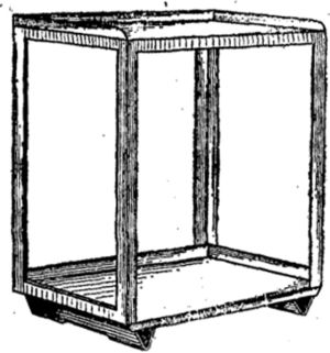
Shelving for horizontal storage of bars
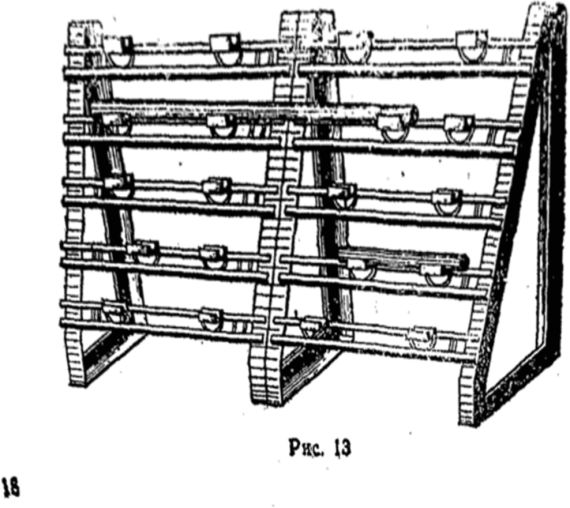
The rack has five rails located at different heights, on which mobile supports are fixed.
The rods are laid on supports, the location and number of which is determined in each case separately. The design provides for the possibility of connecting rack sections along the length. On fig. 13 shows two sections connected to each other.
The details of the rack are made of a bent profile and a corner. The support prism is made of wood impregnated with phenol-formaldehyde resin.
2. Calculation of norms of time
3. Calculation of processing modes
Processing modes should be determined for each operation separately, broken down into transitions.
Parameters of processing modes that include:
Machining parts on metal-cutting machines - tool life, depth of cut, feed, cutting speed, rotational speed of the part (or tool), cutting power;
Welding (surfacing) manual electric arc - type, brand and diameter of the electrode, welding current strength, polarity;
Welding (surfacing) manual gas - gas burner number, type of flame, brand of filler material, flux;
Automatic surfacing - welding current strength, surfacing speed, surfacing step, height of the deposited layer in one pass, weld position, filler material, etc.;
Metallization - parameters of electric current, pressure and air flow, distance from the nozzle to the part, hour-tota of rotation of the part, feed, etc.;
Galvanic coating - atomic mass, valency, electrochemical equivalent, metal output by current, density, etc.
When performing this calculation, you should focus on finding the components to determine the main (machine) time (T o).
Example. Operation 06 turning
where L, - estimated length of processing , mm, (cutting tool stroke)
i- number of passes (usually i = I);
n, - spindle speed, rpm, (number of revolutions of a part or tool),
S - cutting tool feed mm/rev. See L-3 for details.
In the course project, it is necessary to determine the norms of time for the previously selected 2 - 3 operations (opposite). The norm of time (T n) is determined as follows:
T n \u003d T o + T in \u003d T additional +
where T 0 is the main time (the time during which the shape, size, structure, etc. of the part changes. Machine time (To) is determined by calculation);
T in - auxiliary time (the time that ensures the execution of the main work, i.e. for installation, alignment and removal of the part, turning the data, measuring, etc. (Tv) is determined from the tables);
T additional - additional time (time for maintenance of the workplace, break for rest, etc.)

Where K is the percentage of extra time, taken according to Table. (L-3, p.47, table 7);
T p-z - preparatory - final time (Time to receive the task, familiarize yourself with the drawing, surfacing of the tool, etc. (T p-z) is determined by the tables)
X - the size of the production batch of parts (see section No. 2 of this manual).
You need to know that:
![]()
Where Tsht - piece time.
For detailed information on the determination of Tn, see L-3, o.12-15, etc.
The definition of time holes in the course project (as well as in the P control work) should be performed as follows.
Example 1. Determine piece time (Tsht) for turning
threaded neck of the steering knuckle of a ZIL-431410 car after surfacing.
Operation 06 turning. Processing is carried out from D = 40 mm to
d = 36 mm on length l = 30 mm. Equipment: screw-cutting lathe 1K62,
Initial data
1.1. Detail - swivel fist, threaded turning. necks: D = 40; d=36; l = 30.
1.2. Material - steel, 40X.
1.3. Hardness - HB 241...285,
1.4. The weight of the part is up to 10 kg.
1.5. Equipment - screw-cutting lathe 1K62.
1.6. The cutting tool is a through cutter with a T15K6 plate.
1.7. Installation of the part - in the centers.
1.8. Conditions of processing - without cooling.
2.1. Set the part to the center.
2.2. Turn the threaded neck.
2.3. Remove detail.
3. Calculation of allowances ( h) for processing
h = = =2.0
4.1. Determine the processing length ( L)
L = l + y = 30 + 3.5 = 33.5 mm
where l = 30(length of the threaded neck) ;
y=3.5(the value of the cut and overrun of the cutter, L-3, p. 74, table 38).
4.2. Determine the number of passes ( i) :
i = = = 1 ,
where h = 2(allowance for processing),
t- cutting depth.
When roughing, it is desirable to remove the entire allowance in one pass, so we accept t=h=2
4.3. We determine the theoretical (tabular) feed of the cutter ( S)
S= 0.4 - 0.5 mm/rev(L-3, o. 56, tab. 8.)
4.4. Determine the actual longitudinal feed ( S
S= 0.43, mm/rev.
4.5. Determine the cutting speed ( V) tabular.
V= 143, m/min(L-Z, p. 57, tab. 11).
4.6. Correcting V taking into account the processing conditions of the part.
V= V . TO . TO . TO . K \u003d 143. 1.44. 0.7. 1.0 . 1.0 = 144.2 m/min,
where K = 1.44(L-Z, p. 57, tab. 12);
K = 0.7(- "- p. 58, table. 14);
K = 1.0(- "- p. 59, tab. 15);
K = 1.0(- "- p. 59, tab. 16).
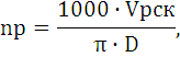
4.7. Determine the number of revolutions of the part ( n)
n==  = 1147.6 rpm
4.8. Determine the actual number of revolutions of the part ( n) according to the passport of the machine (see appendix)
n= 1000 rpm.
5. Calculation of norms of time
5.1 determine the main time (To)

5.2 Determine the auxiliary time (TV)
TV \u003d T set + T pr \u003d 0.48 + 0.7 \u003d 1.18, min
Where T set \u003d 0.48 min - the time to install and remove the part (L-3, p. 77, tab. 43)
T pr \u003d 0.5-0.8 - time associated with the passage (L-3, table. 44)
5.3 Definition of extra time (T add)
5.4 Determine the piece time (Tsht)
Tsht \u003d To + TV + Tdop \u003d 0.08 + 1.18 + 0.16 \u003d 1.42 min
Tsht = 1.42 min
Technical regulation of drilling work
Time norm:
Tn \u003d To + Tv + Td +
Where To is the main time.

Where L is the processing length, mm L = l + y
l is the length of the machined surface according to the detail drawing; y - the amount of penetration and overrun of the drill (reamer, countersink)
i is the number of transitions (or the number of holes on one part);
Passport value of feed, mm/rev.
Select the feed according to the tables, taking into account the material of the workpiece, the material of the cutting part of the tool and the required finish. Coordinate with the passport data of the machine (see Appendix) Accept according to the passport of the machine (see Appendix)
P P - passport value of the machine spindle speed (see Appendix)
Select the tabular value of the development rate
Assign a correction factor;
K 1 - (K m) - depending on the material of the part;
K 2 - (K mr) - depending on the material of the cutting part of the tool
K 3 - (K x) - depending on the state of the surface
K 4 - (K oh) - depending on the presence of cooling.
Corrected cutting speed:
Calculation of the spindle speed of the machine:

D - tool diameter, mm
Coordinate with the passport data of the machine P P (see Appendix)
T in - auxiliary, min
![]()
Auxiliary time for removal and installation. Depends on the method of installation and fastening
Auxiliary transition time
Auxiliary time for measurement. Depends on the type of instrument (see pages 58-60)
Assigned in the presence of measurement transitions;
Т g - additional time, min
![]()
K is the percentage of extra time. For drilling work K = 6% (L-3, p. 47, v. 7)
T p.z. - preparatory - final time, min. Installed on a batch of parts, depends on the type of processing and the method of installing the part
X - The size of the production lot of the part
EXAMPLE 2 Determine the piece time for drilling holes for mounting studs in the rear wheel hub from a diameter of d = 20.08 to D = 26 mm over a length of 20 m. Material - KCh-35 cast iron. Equipment vertical - drilling machine model 2H-135
Additional information:
Number of holes - 6;
Cutting tool drill made of P9 steel
1. Depth of cut

Number of passes - one; number of holes on the part - 6.
2 Gear min/rev.
![]() (L-3, p. 66, tab. 28).
(L-3, p. 66, tab. 28).
According to the passport of the machine = 0.56 mm / rev. (see Attachment)
3. Cutting speed m/min.
Tabular value \u003d 17 m / min (L-3, p. 67, tab. 30)
Cutting speed correction:
K m = 065 - depending on the material being processed;
K mr \u003d 1.00 - depending on the cutting material
K x = 0.75 - depending on the state of the treated surface;
K oh = 1.0 - depending on the presence of cooling.
See L-3, p. 57-59.
Adjust cutting speed:
17 . 0.65. 1.0 . 0.75. 1.0 = 8.28 (m/min)
4. Machine spindle speed
According to the passport of the machine N p \u003d 90 (rpm), see the appendix.
5. Estimated processing length L p = l + y
y = 12 mm (L-3, p. 102, tab. 64)
L p \u003d 20 + 12 \u003d 32 mm.
6 Main time, min,

7. Support time
0.10 + 5 . 0.04 = 0.40 min (L-3, p. 103, tab. 66)
8. Extra time
K \u003d 6% (L-3, p. 47, table 7)
9. Piece time
Tsht \u003d To + TV + Tg \u003d 3.81 + 1.50 + 0.32 \u003d 5.53
Technical regulation of milling work
Nome of time:

That is the main time, min
Where L is the processing length, mm. L = l + y
Sl - length of the machined surface according to the detail drawing
Sy - the amount of infeed and overrun depends on the type of thread
Si - pure passes (number of splines or number of machined surfaces)
Minute feed, mm / min (according to the stonka passport)
![]()
Table value of feed, mm / rev. It is selected taking into account the material of the workpiece, the material of the cutting part of the tool, the required frequency of processing and the type of milling.
Passport value of rotation frequency rpm (see appendix)
Assign correction factors
Adjust cutting speed
Determine the calculated value of the machine spindle speed

D - frieze diameter, mm
The rotation frequency should be coordinated with the passport data of the machine n n . Calculation of the value of the minute feed
![]()
Coordinate the minute feed with the passport data of the machine (see appendix)
T in - auxiliary time is determined according to the tables, taking into account the time for the section and removal of the part, rotation, etc.
Tdop - extra time.
It is determined in the same way as in the previous calculations, taking into account K = 7% - for milling work.
EXAMPLE 3. Determine the piece time for milling the splines of the axle shaft of the car. The spline neck after surfacing is turned to a diameter of 54 mm. Number of slot - 16, length - 85 mm, inside diameter - 46 mm. Equipment - horizontally - milling machine model 6M82G.
Additional information:
Part material - steel 45; = 700 MPa
Tool - disk cutter with diameter D f = 65 mm, number of teeth - 14, cutter material - high speed steel R9
- Depth of cut

Number of transitions i = 16 (according to the number of slots)
2. Feed per revolution of cutter
![]()
3. Cutting speed, m/min. Tabular.
![]() (L-3, p.10, tab.74)
(L-3, p.10, tab.74)
4. Correction of cutting speed
Where K 1 \u003d 0.51 (L-3, p. 57, table 12)
K 2 \u003d 0.7 (L-3, p. 58, table 14)
K 3 \u003d 1.0 (L-3, p. 59, tab. 15)
5. Machine spindle speed

6. Minute gear, S m , mm/min.
According to the passport of the machine = 125 mm / min. (see Attachment)
7. Estimated length of processing
L p \u003d l + y \u003d 85 + 17.5 \u003d 102.5 mm
Where l is the length of the slots;
y - increase in cutter time (l 1) and cutter output (l 2) - overrun;
l 1 = 15 (L-3, p. 114, tab. 79)
l 2 = 2.5 (L-3, p. 114, tab. 79)
8. Regular time

9. Auxiliary time
T in \u003d T oy in + T pr in \u003d 0.6 + 3.8 \u003d 4.4, min.
Тоу в = 0.6 (L-3, p. 115, tab. 81).
T pr in \u003d 0.8 + 0.2. (n - 1) = 0.8 +0.2 . (16 - 1) = 3.8,
Where n = 16 (number of slots).
10. Extra time
T add \u003d 
Where K \u003d 7% (L-3, p. 47, table 7).
11. Piece time
T pcs \u003d T o + T in + T additional \u003d 13.12 + 4.40 + 1.23 \u003d 18.75, min. T pcs = 18.75, min.
Technical regulation of grinding works.
Cylindrical external grinding with cross feed on double table stroke
regular time

where L p is the length of the table stroke when the circle exits in both directions L p \u003d l + B
l - length of the processed surface, mm
B - width (height) of the grinding wheel, mm
When the circle exits in one direction L p \u003d l + B / 2
When grinding without leaving the circle L p \u003d l - B
z - machining allowance per side, mm
n and - rotational speed of the workpiece, rpm
![]()
v and - product speed, m/min.
D - diameter of the workpiece, mm
Match the speed with the nameplate data of the machine n and
S pr - longitudinal feed, mm / rev
S t - grinding depth (cross feed)
K - coefficient taking into account wheel wear and grinding accuracy
K = 1.1-1.4 for rough grinding
K = 1.5-1.8 for fine grinding
External cylindrical plunge grinding 
S p - radial feed, mm/rev
Round internal grinding

L p \u003d l m - 1 / 3V - for through holes
L p \u003d l m - 2 / 3V - for blind holes
Z - machining allowance, mm

Cylindrical centerless grinding with longitudinal feed

l m - length of the polished product, mm
S pr.m - minute longitudinal feed mm / min
Round centerless plunge grinding

Jhd t vr \u003d 0.01-0.02 min - plunge time
Z - allowance for diameter, mm
S ppm - transverse minute feed. mm/min

Where S p - rational transfer mmob
П - frequency of rotation of the grinding wheel, rpm

U cr - circumferential speed of the circle m / s
D - circle diameter (Take D = 300 mm)
Determine the piece time (T pieces) for fine grinding of the neck under the outer bearing of the steering knuckle of the ZIL-431410 car. Grinding allowance 0.017 Equipment - circular grinding machine model 3B151. Neck length l = 28, diameter D = 39.997, d = 39980
1. Initial data
1.1 Detail: Swivel knuckle of a ZIL car - 431410. D = 39.997, d = 39980, l = 28, z = 0.017
Calculation of processing modes and time standards
L-4 provides recommendations for calculating the time norms for the main types of repair work with examples. Reference data are given according to the L-4 reference book. This does not exclude the possibility of using other reference literature on the rationing of repair work.
Technical regulation of turning works
Time norm:
where T o - main time (machine), ![]()
L p - estimated length of processing, mm. It is determined taking into account the type of turning (turning, boring, cutting ends, grooving).
where l is the length of the machined surface according to the detail drawing;
y is the value of the cut and run of the cutter;
i – number of passes (usually i=1);
S p about - passport value of the feed, mm / rev.
Select the feed S p o according to the tables, taking into account the material of the workpiece, the material of the cutting part of the tool and the required finish.
For processing rough and intermittent surfaces, reduce the tabular feed value by 20-35%. Coordinate S p about with the passport data of the machine (see Appendix). Take S p about = ... mm / rev.
N p - passport value of the machine spindle speed;
select the tabular value of the cutting speed V p t;
assign correction factors:
K m - depending on the material of the workpiece;
K mr - depending on the material of the cutting part of the tool;
K x - depending on the state of the treated surface;
K oh - depending on the availability of cooling;
Adjust cutting speed:
V r ck \u003d V r t ∙K m ∙K mr ∙K x ∙K oh;
Determine the calculated value of the machine spindle speed:
where D is the diameter of the workpiece.
Coordinate with the passport data of the machine n p.
T in - auxiliary time, min.
T in \u003d T in su + T in pr + T in meas, min.
T in su - auxiliary time for installation and removal of the part, depends on the method of installation and fastening;
T in pr - auxiliary time for the passage;
T in meas - auxiliary time for measurements, depends on the method of measurement.
Assigned when there is a measurement transition.
T d - additional time, min.
T d ![]()
where K is the percentage of overtime. For turning works K=8%;
T p.z. - preparatory and final time. It is installed on a batch of parts, depending on the type of processing and the method of installing the part;
P p - the size of the production batch of parts.
Example 1 Determine the piece time for turning the threaded neck after surfacing at the stub axle of the ZIL-4314.10 car. Processing is carried out from D=42 mm to D=36 mm at a length of l=32 mm. Equipment: screw-cutting lathe 1K62.
Additional information:
The cutting tool is a through cutter with a hard-melting plate T5K10;
Processed material - steel 40X;
B c \u003d 400 MPa.
Solution:
1. Depth of cut
![]()
Number of passes i=1.
2. Feed S, mm/rev. with rough turning and cutting depth t=3 mm and b c =400 MPa.
Table value S t \u003d 0.3-0.6 mm / rev.
According to the passport of the machine S p about =0.3 mm / rev.
3. Cutting speed V, m/min.
Table value V t \u003d 198 m / min.
Cutting speed correction:
K m \u003d 1.65 - depending on the material being processed;
K mr \u003d 0.95 - depending on the material of the cutter;
K x \u003d 0.65 - depending on the state of the treated surface;
K oh \u003d 1.0 - depending on the presence of cooling.
Corrected cutting speed:
V p ck \u003d 198 ∙ 1.65 ∙ 0.95 ∙ 0.65 ∙ 1.0 \u003d 201.74 m / min.
4. Part rotation speed n, rpm:
According to the passport of the machine n p \u003d 1600 rpm. (see Attachment)
5. Estimated length of processing
L p \u003d l + y \u003d 32 + 5 \u003d 37 mm,
where y=5 mm.
6. Main (machine time):
![]()
7. Auxiliary time.
2.8.1 Rationing of operations on universal machines with manual control.
Definition of the main (technological) time.
The main time is determined by the calculation formulas for the corresponding type of work and for each technological transition (T o1, T o2, ..., T o n).
The main (technological) time for the operation:
where n is the number of technological transitions.
Definition of auxiliary time.
For equipment designed to perform single-transition work with constant modes in one operation (multi-cutting, hydrocopying, gear-cutting, broaching, threading machines), the auxiliary time T is given for the operation, including the time for installing and removing the workpiece.
Auxiliary time for the operation is determined by the formula:
where t mouth - the time to install and remove the part, given by type of fixture, regardless of the types of machines, min;
t lane - the time associated with the transition, given by machine types, min;
t' lane - time not included in the complex of time associated with the transition, min;
t meas - time for control measurements after the end of surface treatment. The time for control measurements is included only in those cases when it is not overlapped by the main time or is not included in the complex of time associated with the transition, min;
Kt in - correction factor for auxiliary time, min.
Definition of operational time:
 , min
, min
where T about - the main time for processing;
T in - auxiliary time for processing, min.
Determination of time for maintenance of the workplace and personal needs.
Time for maintenance of the workplace, rest and personal needs is determined as a percentage of the operational time according to normative reference books.
Standard time:
where α obs and α voln are the time for servicing the workplace and the time for rest and personal needs, expressed as a percentage of the operational time.
Definition of preparatory-final time.
The preparatory and final time T pz is normalized for a batch of parts, and part of it per one part is included in the piece-calculation time:
 , min
, min
where n d is the number of parts in the batch.
2.8.2 Normalization of operations on universal and multi-purpose CNC machines.
The norm of time and its components:
 , min
, min
where T tsa - the cycle time of the automatic operation of the machine according to the program, min.
 , min
, min
where T o - the main (technological) time for processing one part is determined by the formula:
 , min
, min
where L i is the length of the path traversed by the tool or part in the feed direction when processing the i-th technological section (taking into account the plunge and overrun), mm;
S mi - minute feed on the i-th technological section, mm/min;
Tm-v - machine auxiliary time according to the program (for supplying a part or tool from the starting points to the processing zones and retraction, setting the tool to a size, changing a tool, changing the magnitude and direction of feed), the time of technological pauses, min.
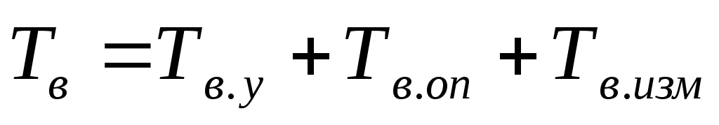 , min
, min
where T v.y is the time for installing and removing the part manually or with a lift, min;
T v.op - auxiliary time associated with the operation (not included in the control program), min;
Т v.meas – auxiliary non-overlapping time for measurements, min;
K t in - correction factor for the time of performing manual auxiliary work, depending on the batch of workpieces;
α tech, α org, α otd - time for technical, organizational maintenance of the workplace, for rest and personal needs for one-stop service, % of operational time.
The norm of time for setting up the machine is presented as the time for preparatory and final work on the processing of batches of parts, regardless of the size of the batch, and is determined by the formula:
where T p-31 - the norm of time to receive an order, technological documentation at the beginning of work and delivery at the end of the shift, min; T p-31 = 12min;
T p-32 - the norm of time for setting up a machine, fixture, tool, software devices, min;
T pr.arr - the norm of time for trial processing (of the first part), min.
Technical regulation.
Technical standardization is carried out for operation 005 "Lathe with PU" and operation 030 "Complex with PU".
1. Operation 005 "Turning with PU".
1.1 The main (technological) processing time for each transition is determined by the formula:
 , min
, min
 , min
, min
where l cut - cutting length, mm
y, ∆ - infeed or overrun value, mm
L is the path length of the cutting part of the tool, mm.
L 1 \u003d (113-70) / 2 + (65-33) / 2 + 4 \u003d 42mm;
L 2 \u003d 35 + 5 +2 + 4 + 2.5 + 4 \u003d 57mm;
L 3 \u003d (113-70) / 2 + 4 \u003d 11mm;
L 4 \u003d 57 + 4 \u003d 61mm;
L 5 \u003d 57 + 4 + 1 + 4 \u003d 66mm.
T o1 \u003d 42 / (0.6 × 315) \u003d 0.22 min;
T o2 \u003d 51 / (0.6 × 500) \u003d 0.27 min;
T o3 \u003d 11 / (0.15 × 500) \u003d 0.14 min;
T o4 \u003d 61 / (0.3 × 800) \u003d 0.25 min;
T o 5 \u003d 66 / (0.15 × 1250) \u003d 0.35 min.
1.2 The main processing time per operation is determined by the formula.