Page 2 of 2
13. Disconnect connector 1 from the controller idle move. Unscrew nut 2 and remove the "mass" wires from the stud at the rear end of the receiver.
14. Disconnect connector 1 from the air temperature sensor. Loosen clamp 2 and remove the coolant supply hose from the heater tap fitting.
15. Disconnect connectors 1 from injectors. Unbend the holders 2 of the wiring harness and remove the harness from the holders. Move the wiring harness away from the engine.
Then disconnect the muffler intake pipe from the exhaust manifold, disconnect the hose from the throttle body, remove the radiator inlet pipe, remove the generator.
1. Remove camshafts.
2. Loosen clamps 1 and remove hoses 2 and 3 from throttle body fittings.
3. Remove thermostat with housing.
4. Remove the spark plugs.
5. To turn away bolts 1 fastenings of a head of the block. Remove bolts 1 and washers.
6. Remove the cylinder head and head gasket.
Do not drive a screwdriver or any other tool between the block head and the cylinder block, as this can damage the surface of the block head adjacent to the cylinder block.
Installation
Install the block head in the reverse order of removal.
The order of an inhaling of bolts of fastening of a head of the block is shown in drawing.
Tighten the block head bolts in two stages:
1st stage - 40–60 N m (4.0–6.0 kgf m);
2nd stage - 130–145 N m (13.0–14.5 kgf m).
Recording for yourself. Often there is no torque table for the 406 engine at hand, and the book is far away. Easy to watch on your phone.
What is the wide torque range for?
For the fact that all dynamos have an error. It is better to take the moment in the middle of the range.
Minimum allowable-maximum tightening torque. For example: 100-110 Nm.
Reminder:
In places where there are many tightening points, for example, the intake manifold. It is better to go through the final moment several times. The dots in the middle "sag".
Attention! Intentionally inaccurate.
Since - 1 kilogram-force-meter (kgf m) = 9.80665 newton meters (N m)
In places with large moments, more accurate values are given.
An example of more accurate calculations:
10-11 kgf m = 98-108 N m
List of tightening torques (table):
- Main bearing cap bolt. 10 points. M12x1.25. 98-108 Nm
- Nut of a bolt of fastening of covers of rods. 8 points. M10x1. 67-74 Nm
Bolt of fastening of a head of the block of cylinders. 10 points. M14x1.5
– first stage 40-60 Nm
- second stage 127-142 Nm
Degrease surfaces.
It is better to break it down into more stages. There is nowhere to hurry.
After pulling the final moment, you need to go through all the points again.
Since the gasket is crumpled unevenly and the tightening torque is weakened.
Cylinder head tightening order 406
Bolt of fastening of a cover of a camshaft (yoke). 20 points. M8. 19-23 Nm
Clean the threaded holes of oil. A syringe (after biting off the bevel at the needle) or a rag with a screwdriver.
These covers very fragile. You need to unscrew slowly and all at the same time.
I unscrew it with a snake at all points.
It is not advisable to unscrew the cover one at a time. In the end, the load will focus on one lid and it will burst.
Tighten all the bolts at the same time until the planes of the cylinder head and the covers come into contact.
Then with a dynamo key at all points I pass several times.
Crankshaft coupling bolt (ratchet). 1 point. M24x2. 102-126 Nm
Everything is done logically. The bolt should tighten itself when the engine is running.
Unscrew counterclockwise.
The crankshaft must not be turned counterclockwise!
Put it in 5th gear and unscrew the crankshaft bolt.
Bolt of fastening of a cogwheel of a camshaft. 2 points. M12x1.25. 56-62 Nm
- A bolt of fastening of gear wheels of an intermediate shaft. 2 points. M8. 22-27 Nm
Flywheel bolt. 6 points. M10x1.25. 72-80 Nm
- Clutch pressure plate mounting bolt. 6 points. M8. 20-25 Nm
- Clutch housing bolt. 6 points. M10. 42-51 Nm
- A bolt of fastening of a support of a fork of deenergizing of coupling. 1 point. M10x1. 42-51 Nm
- A bolt of fastening of the amplifier of a crankcase. 6 points. M10. 29-36 Nm
- Stuffing box fixing bolt. 6 points. M6. 12-18 Nm
Nut of fastening of an inlet pipe. 5 points. M10x1. 29-36 Nm
(The pipe that is in contact with the cylinder head)
- A nut of fastening of a receiver to an inlet pipe. 5 points. M8x1. 19-23 Nm
- Nut of fastening of an exhaust manifold. 8 points. M8. 20-25 Nm
- Bolt of fastening of a cover of a head of the block of cylinders. 8 points. 5-12 Nm
when ensuring tightness, a torque of 3 Nm is allowed
- Oil sump bolt. 11 points. M8. 12-18 Nm
when tightness is ensured, a torque of 6 Nm is allowed
- A bolt of fastening of a forward cover of a head of the block of cylinders. 4 points. M8. 22-27 Nm
(Front covers can be glued with sealant, no need for much force. 8-14 Nm)
- A bolt of fastening of a pulley to the water pump/pump. 3 points. M8. 22-27 Nm
- Water pump/pump mounting bolt. x points. M8. 22-27 Nm
- A nut of fastening of arms of the generator. 2 points. M8. 12-18 Nm
- Mounting bolt tension roller. 1 point. M8. 14-18 Nm
Bolt of fastening of a fuel line with atomizers. 2 points. M6. 5-8 Nm
(O-rings of injectors can be lubricated with engine oil)
- Bolt for fastening inductive sensors. 3 points. M6. 5-8 Nm
- Spark plug. 4 points. M14x1.25. 31-38 Nm (aluminum cylinder head, preferably 28-30 Nm)
- Starter bolt. 2 points. M10. 67-75 Nm
For other threaded connections:
for M6 - 6–8 Nm
for M8 - 14–18 Nm
for M10 - 28–36 Nm
for M12 - 50–62 Nm
Reminder:
After completing the work, bring the dynamo key to its original state.
Data taken:
1) Manual for the repair, operation and maintenance of the car Volga Gas 3110. ISBN 5-8115-0011-4
2) GAZ-3110, -3102 "Volga": Operation, maintenance and repair manual. ISBN 978-5-88924-171-3
3) a little away
Page 1 of 2
Removal and installation of the cylinder head of the ZMZ-406 engine
Withdrawal
The block head can be removed with the receiver and exhaust manifold.
If the head of the block is removed from the engine installed on the car, you must first perform the operations indicated in the subsection " Removing and installing the engine".
Then disconnect the muffler intake pipe from the exhaust manifold, disconnect the hose from the throttle body, remove the radiator inlet pipe, remove the generator.
1. Remove camshafts.
Disassembly
1. Unscrew nuts 1 and remove phase sensor shield 5, bracket 2 for lifting the engine and exhaust manifold 6.
Remove the exhaust manifold gaskets. Unscrew bolt 3 and remove phase 4 sensor.
Unscrew emergency oil pressure sensors 7 and oil pressure indicator 8.
2. Loosen the clamp 1 and remove the hose from the idle speed regulator pipe.
Unscrew nuts 2 and remove receiver 3 from intake pipe.
Remove the receiver gasket.
Remove the intake pipe gasket.
4. To turn away bolts 1 and to remove a back cover 2 of a head of the block.
Remove cover gasket.
5. To take out hydropushers of 1 valves.
G It is more convenient to take out the pushers with a magnet or a suction cup.
Hydraulic pushers cannot be interchanged, therefore, before removing them, they must be marked in order to be installed in their place during assembly.
Keep hydraulic pushers in the same position as they are on the valves so that oil does not leak out of them.
Install the valve spring compressor on the head of the block.
After compressing the valve springs with the help of the tool, remove the crackers 2 valves.
Then, gradually loosening the pressure on the handle of the device, completely open the valve springs.
Remove tool from block head. Take out the plate 3 of the valve springs. Then remove the outer and inner valve springs.
6. Remove the valve stem seal 1.
8. Remove the valve from the side of the combustion chamber.
9. In the same way to remove other valves.
Before removal, mark all valves so that they can be reinstalled during assembly.
Page 1 of 2
Removal and installation of camshafts of the ZMZ-405, ZMZ-406 engine
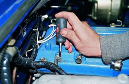
1. We remove the tips of the spark plugs together with the high-voltage wires, the ignition coils (you can only disconnect the connectors by leaving them on the valve cover), the throttle cable and, having disconnected the wires from the sensors of the lubrication and cooling systems, remove the wiring harness from the brackets of the head cover.
2. Drain the coolant and remove the upper radiator hoses and the mass air flow sensor along with the air ducts.
|
3. Using a screwdriver, loosening the clamps, remove the large ventilation hose |
4. |
|
|
|
 Remove the small crankcase ventilation hose.
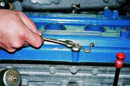 5. With a 12 key, we unscrew the screws securing the block head cover
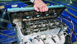 6. Remove the block head cover
7. With the head at 36, we set the crankshaft to the TDC position of the compression stroke of the first cylinder by turning it by the pulley mounting bolt (the mark on the crankshaft pulley should coincide with the protrusion on the front cover of the cylinder block, and the marks on the camshaft sprockets should be at the upper edges of the head block).
|
9. Remove the upper hydraulic tensioner (see Removal and installation of hydraulic tensioners). |
|
|
|
|
|
|
|
|
|
 8. Using a 12 key, unscrew the four bolts and remove the front cover of the block head.
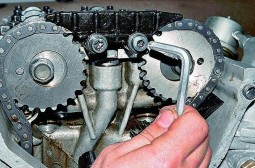 10. Using a 6-point wrench, unscrew the two screws and remove the upper chain guide.
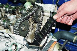 11. Having unscrewed the two screws with a 6-point wrench, remove the middle chain guide.
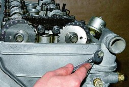
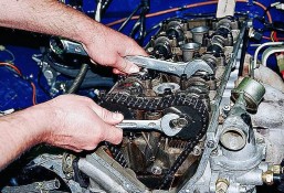 12. Using a 17 key, unscrew the bolt securing the exhaust camshaft sprocket, holding the shaft with a 30 key.
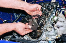 13. Remove the asterisk. Similarly, remove the sprocket from the second camshaft.
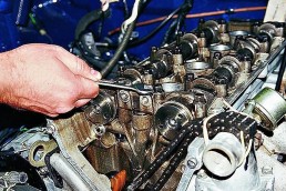 14. Using a 12 key, we unscrew the four bolts securing the front cover of the camshafts. Consistently, half a turn, loosen the bolts securing the camshaft covers until the valve springs stop pressing the shafts and unscrew the bolts.
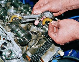 15. Remove the front cover and remove the plastic half rings